Services Corporation International (SCI) Headquaters
Services Corporation International (SCI) Headquaters
Project Details:
Owner: Hines
General Contractor: D.E. Harvey Builders
Date of Work: October 2024 - November 2024
Engineer: Walter P. Moore
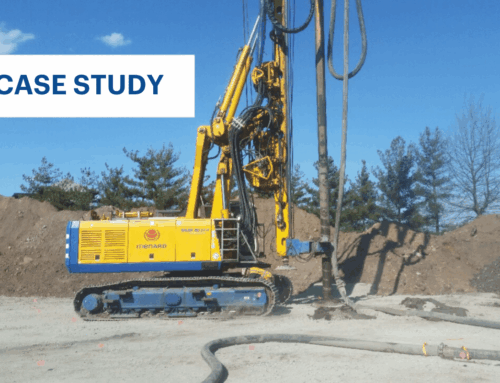
Approximate Key Quantities: Controlled Modulus Column (CMC)® rigid inclusions - 810 EA.
Description:
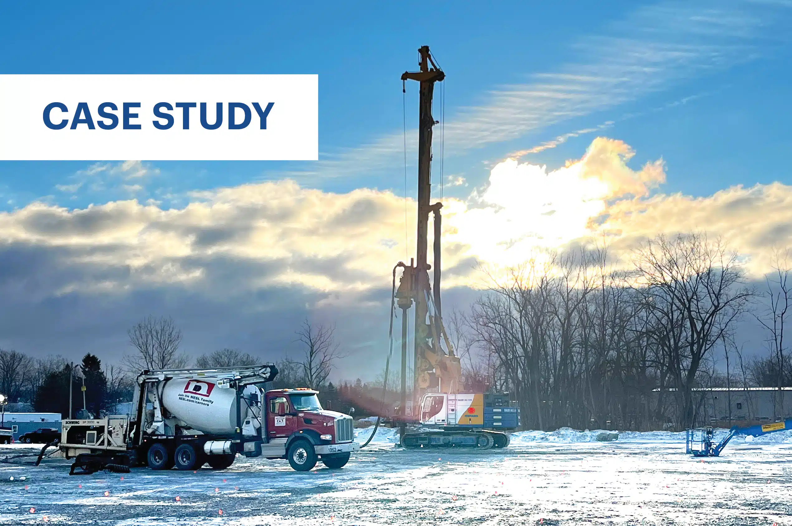
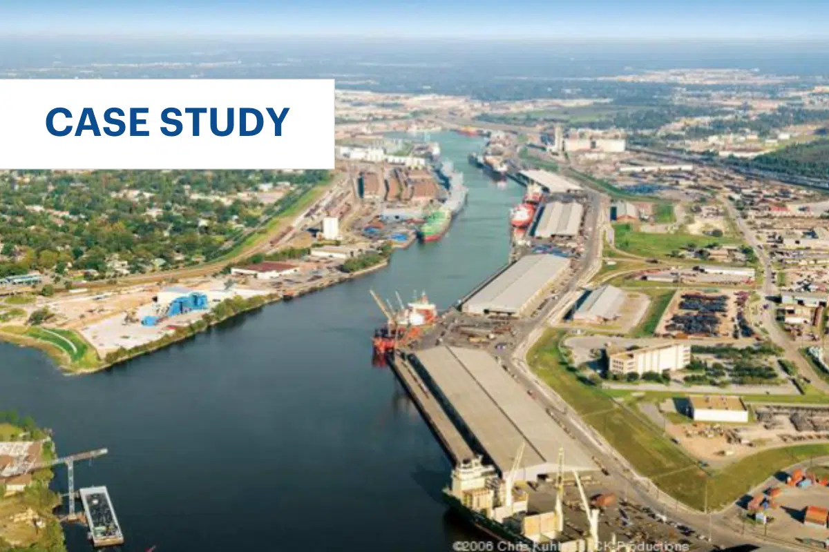
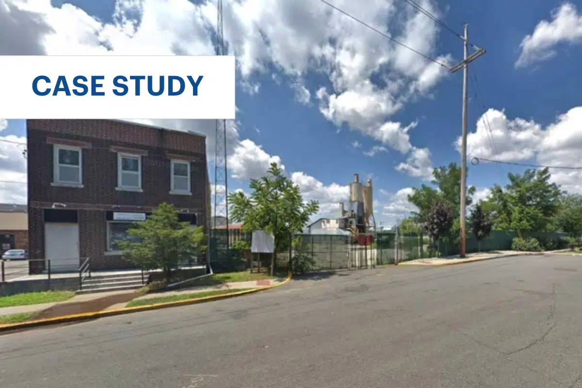
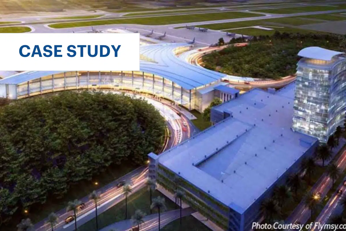
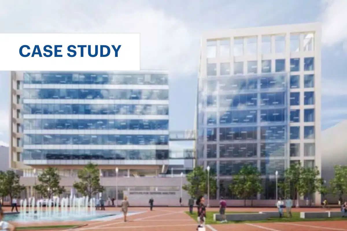
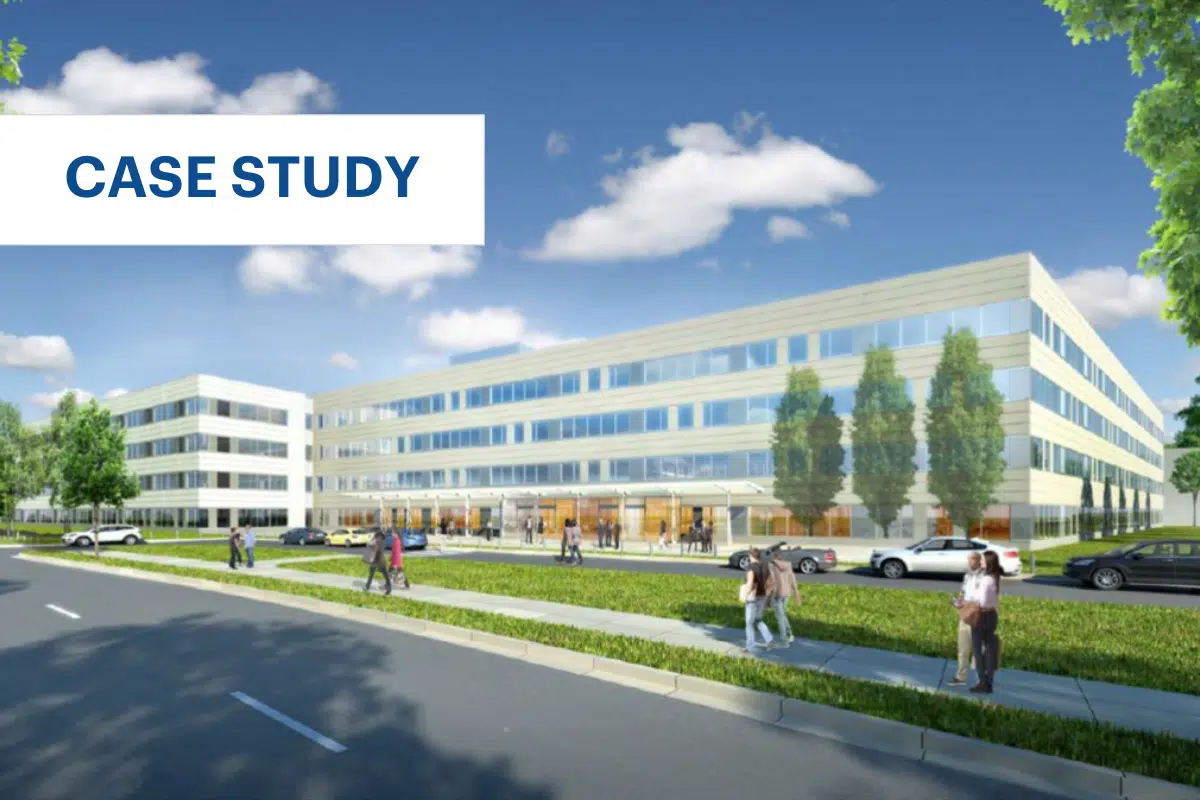
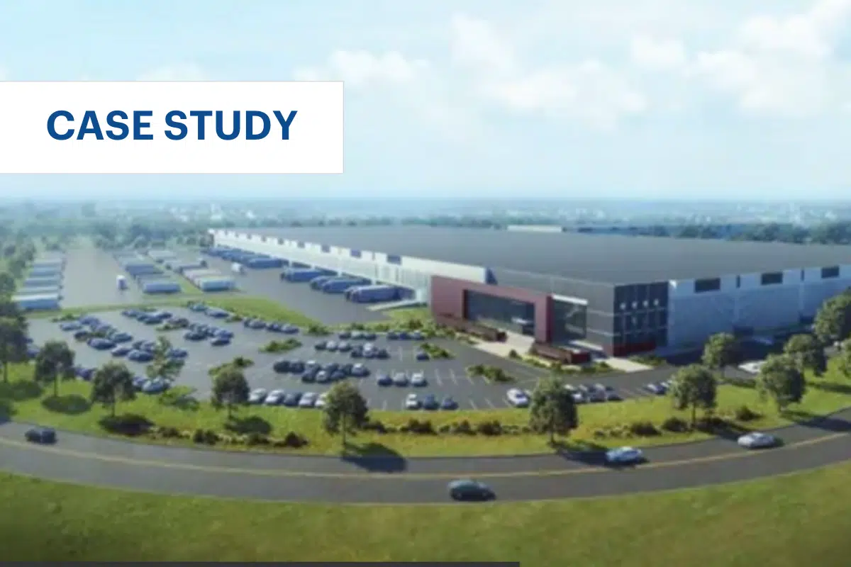
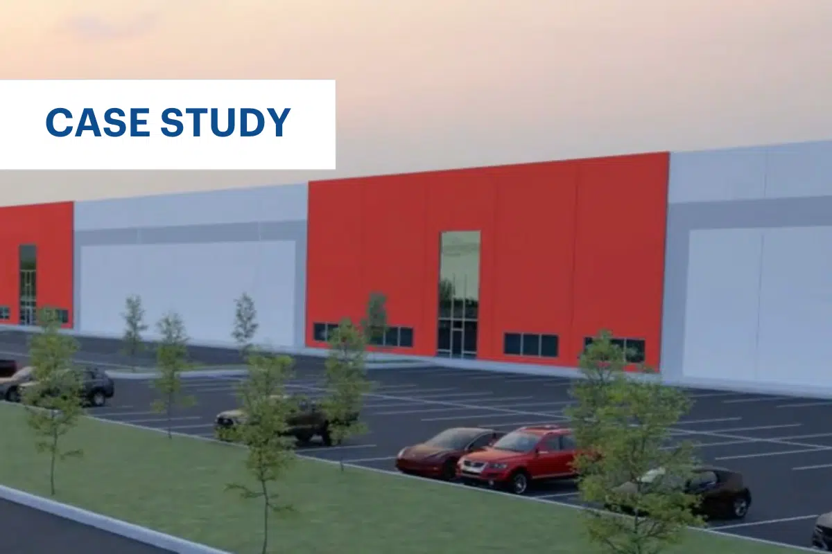
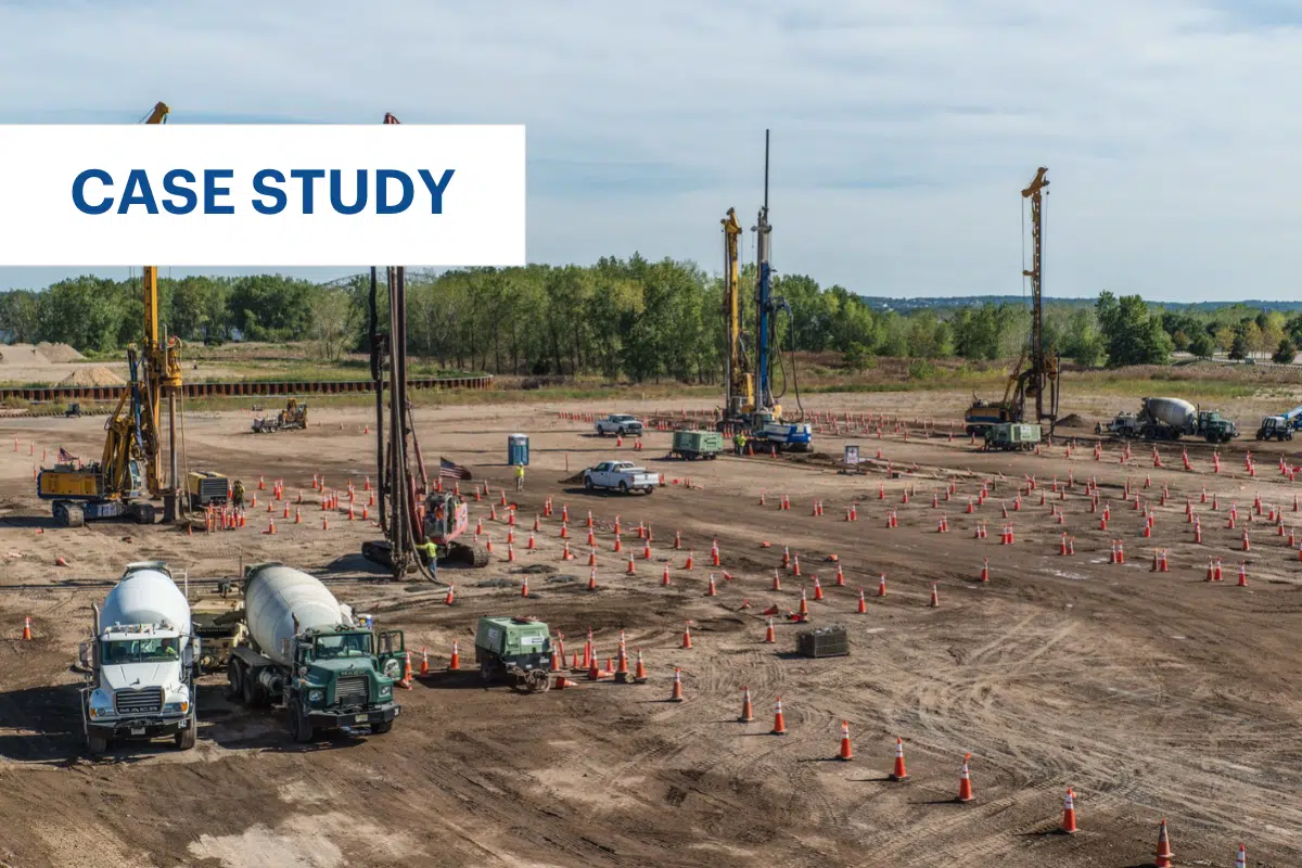
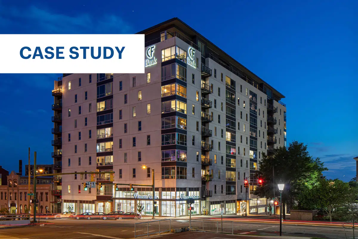
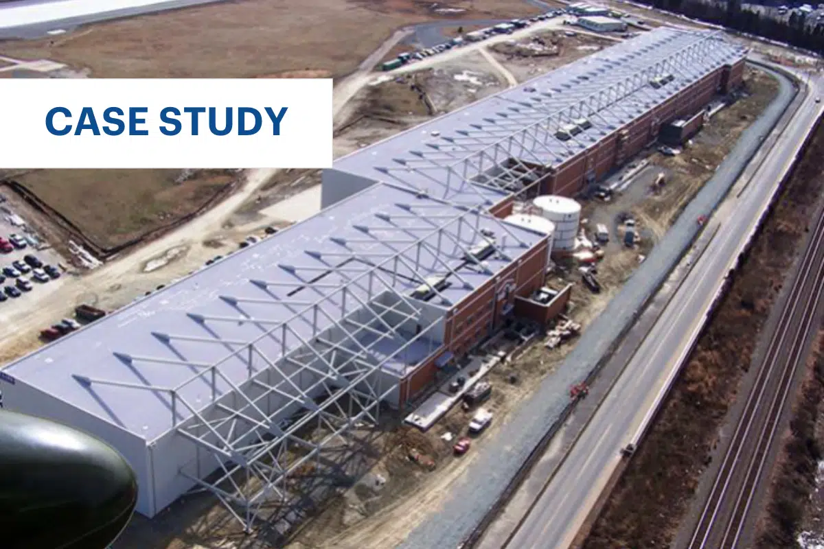
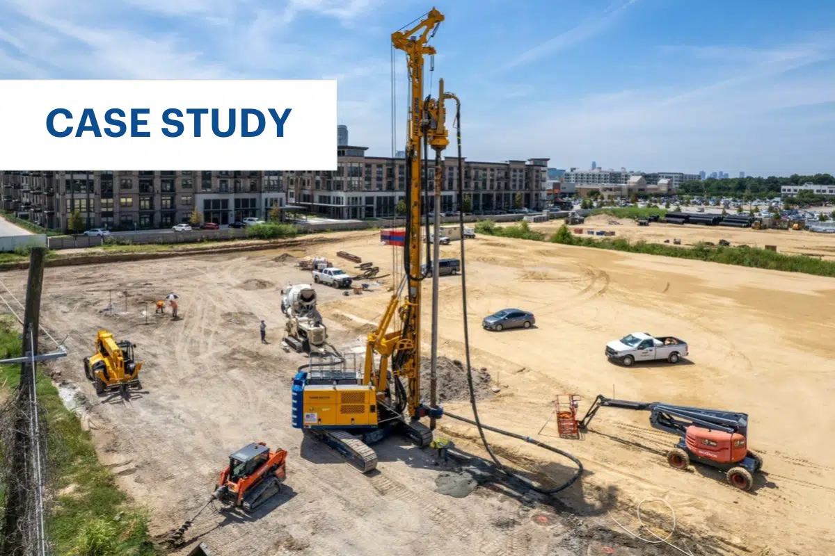
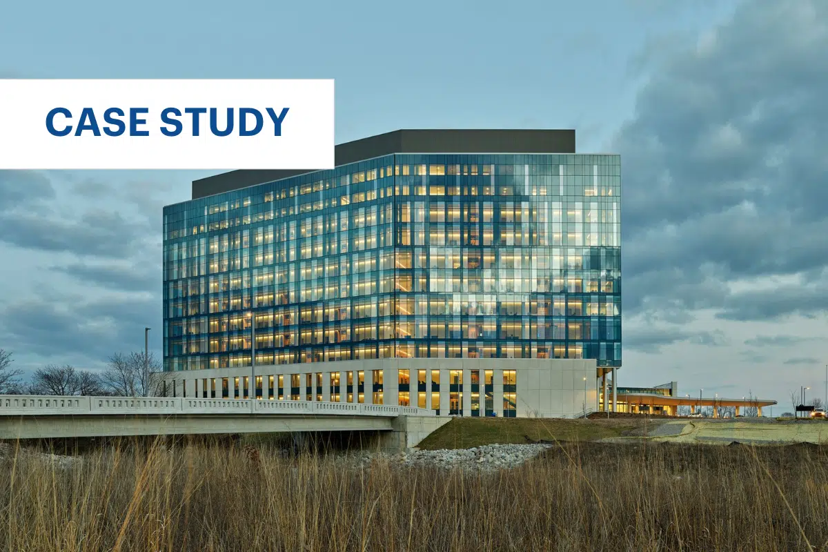
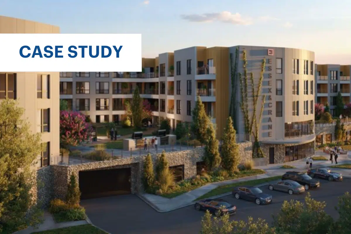
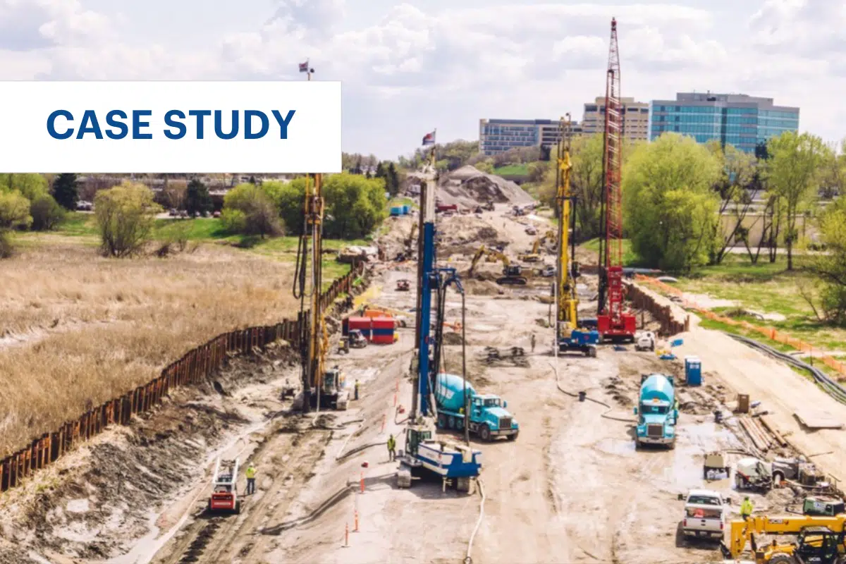
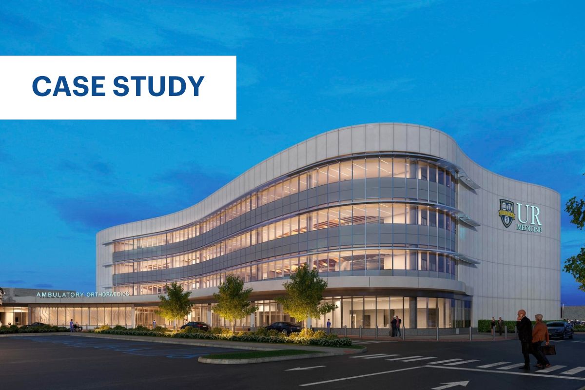
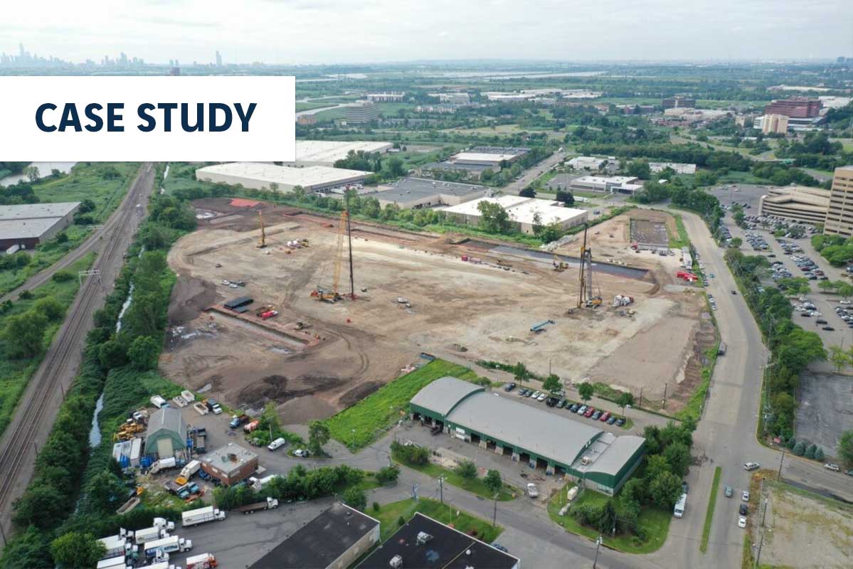
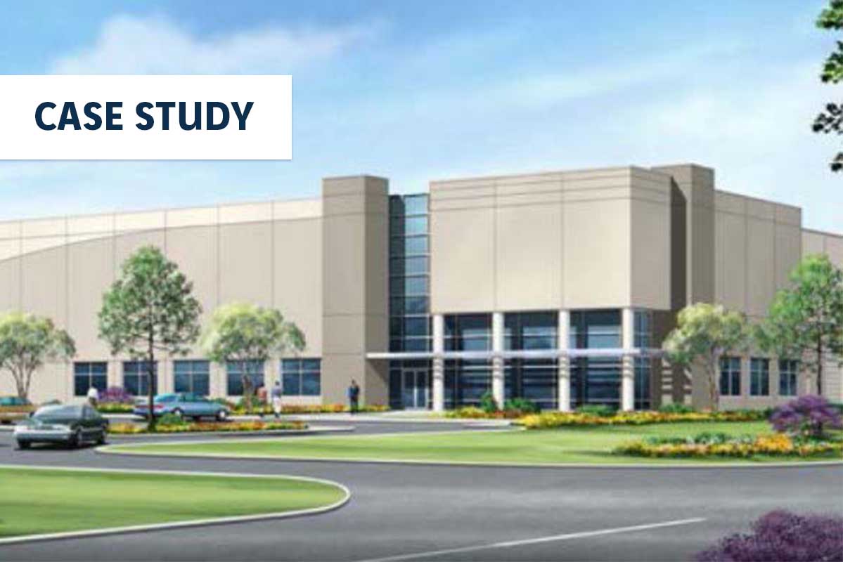
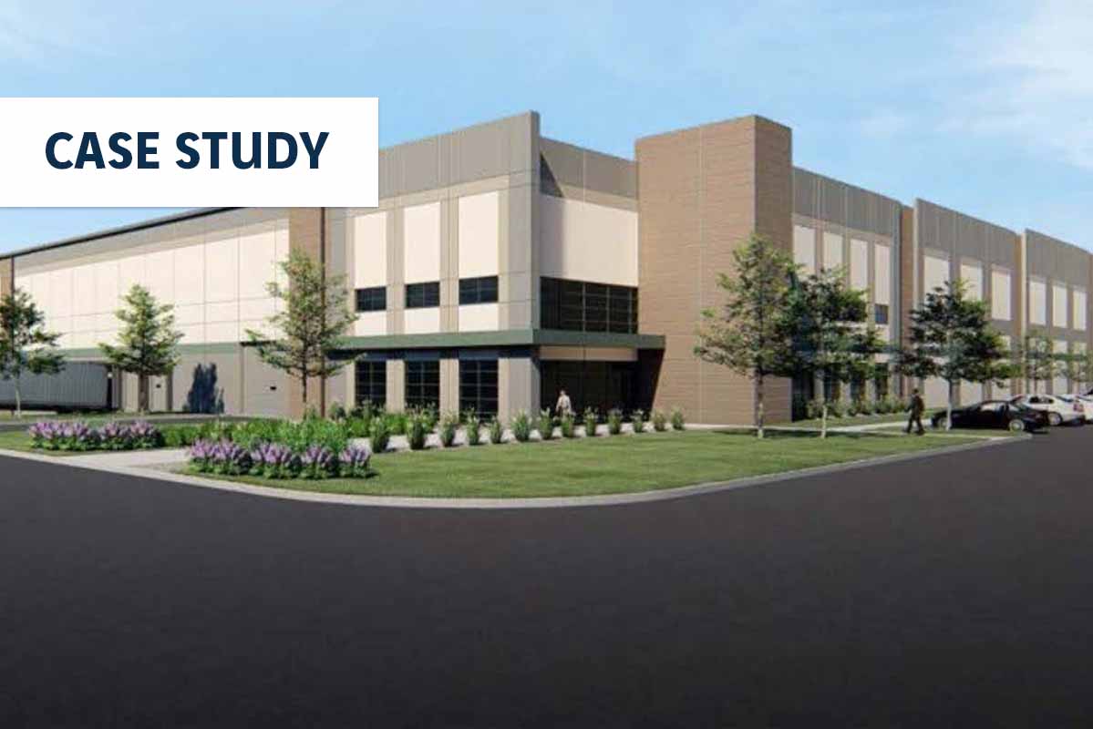
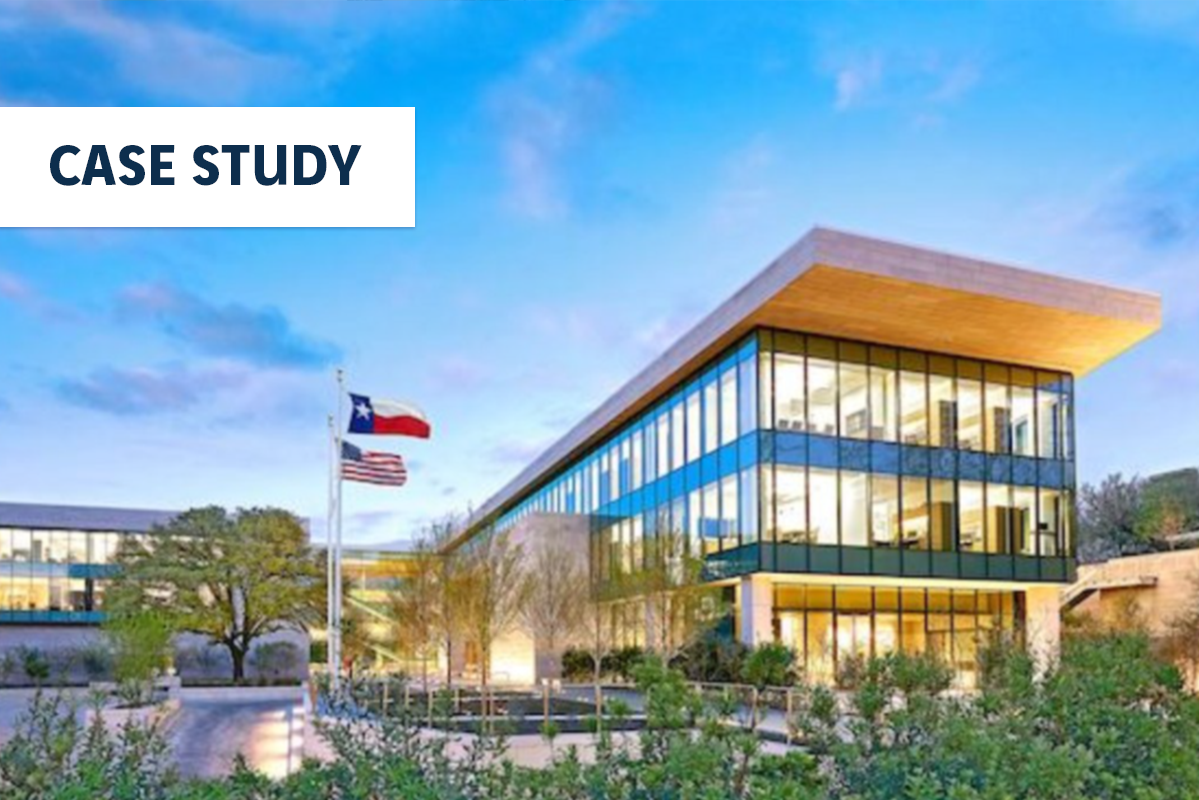
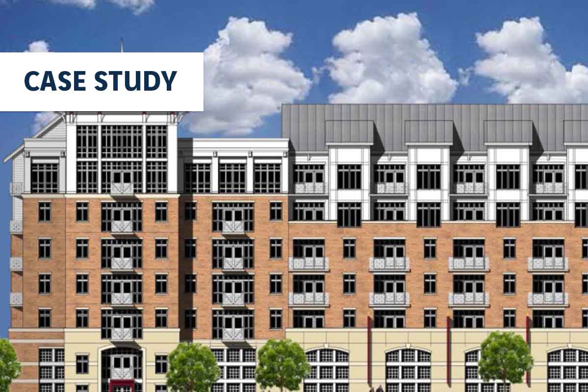
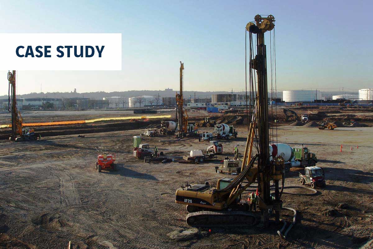
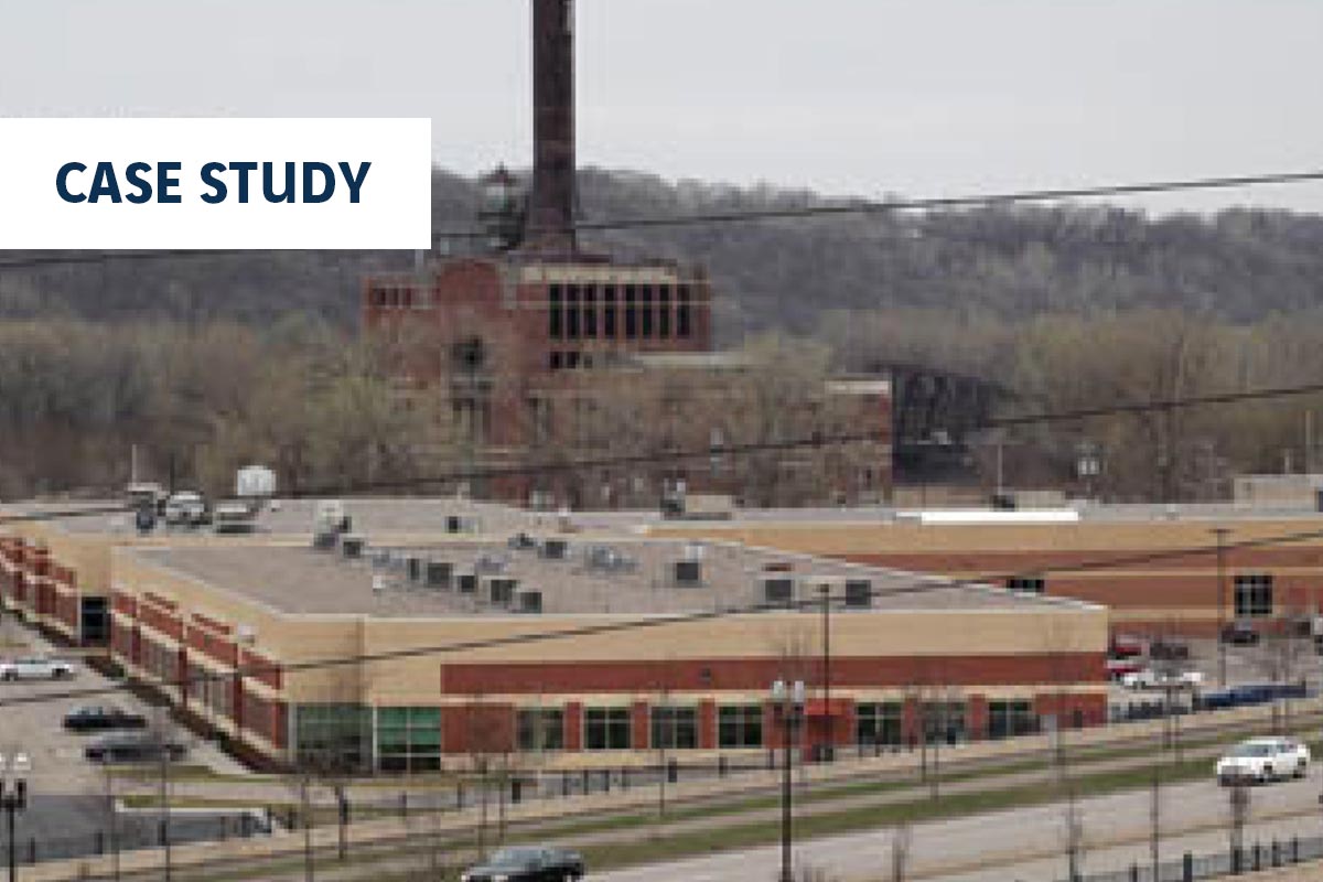
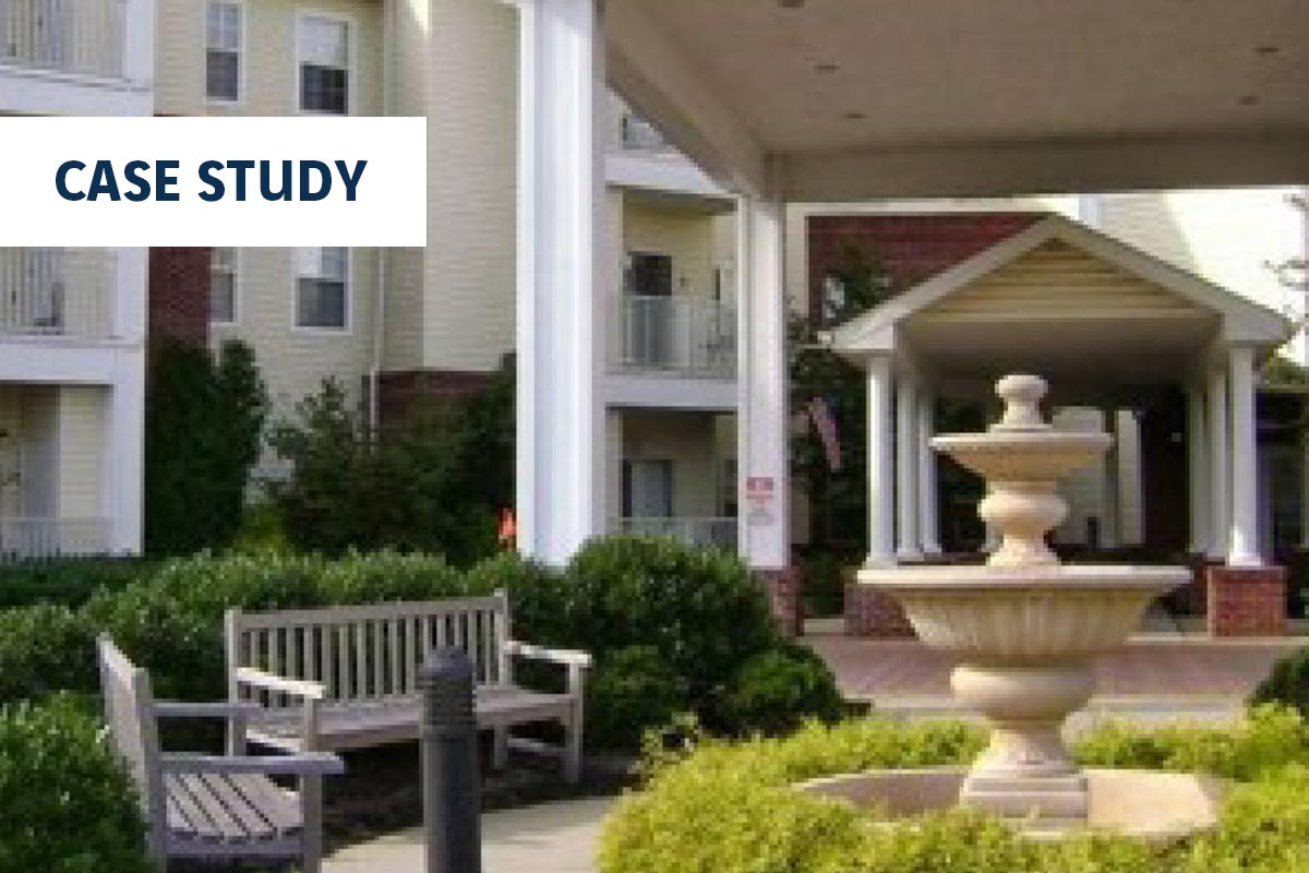
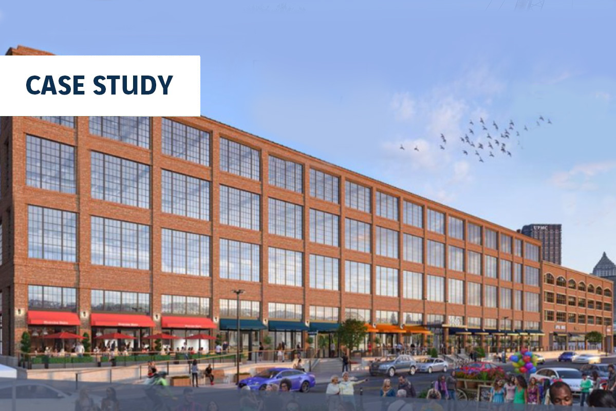
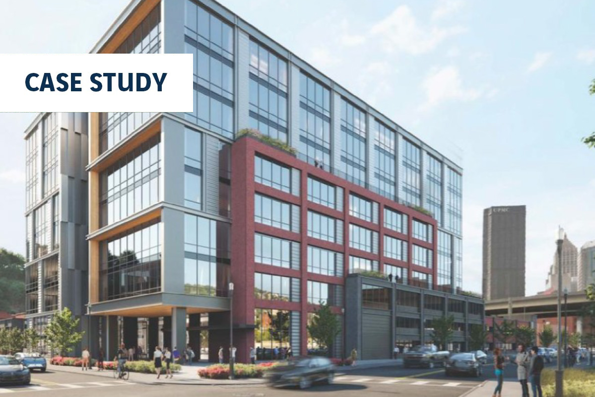
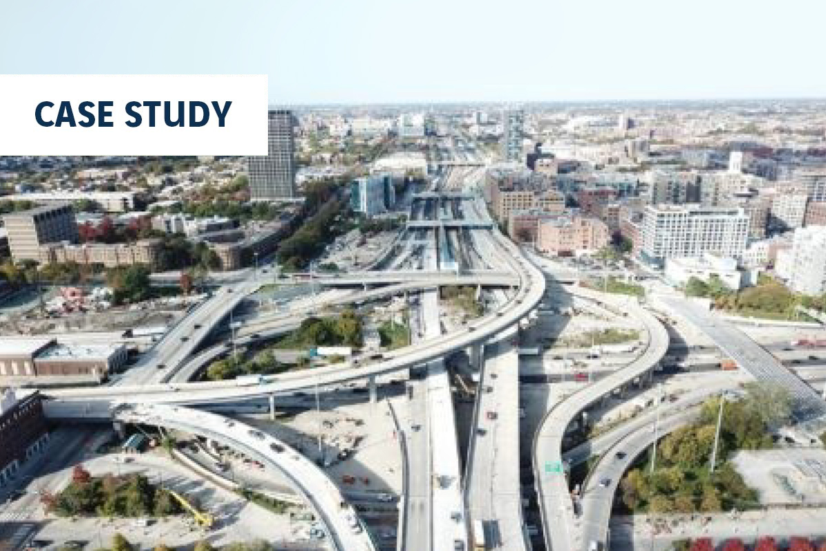
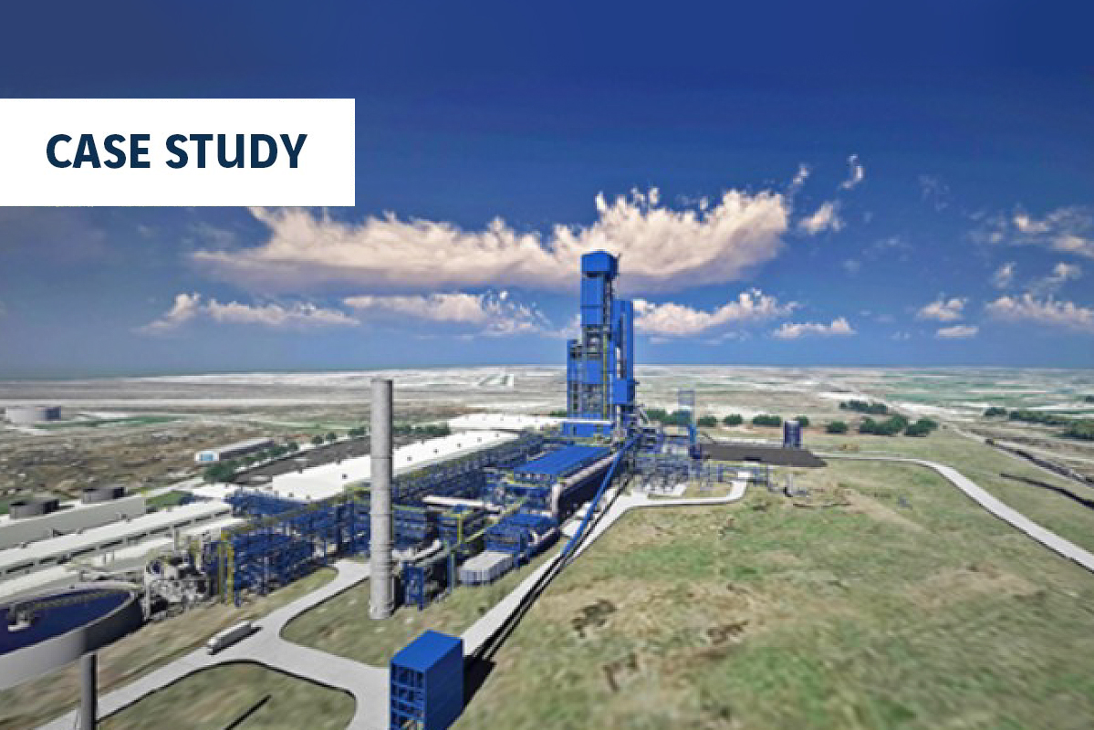
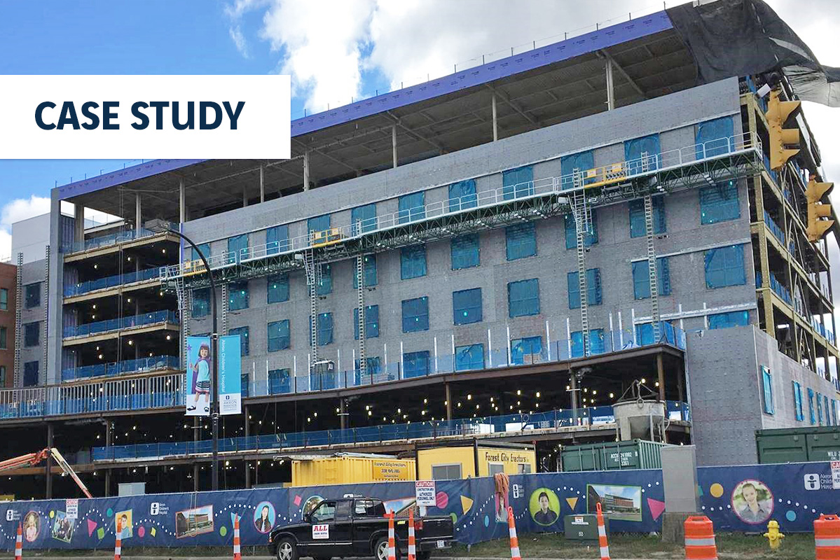
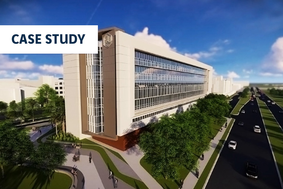
Service Corp. International, the Houston-based funeral services company and one of the city’s largest publicly traded companies, planned to develop a new corporate headquarters. SCI is North America’s leading provider of funerial services. SCI’s new tower, developed by Hines, is planned for the former site of KHOU-TV studios and is located next to SCI’s current offices.
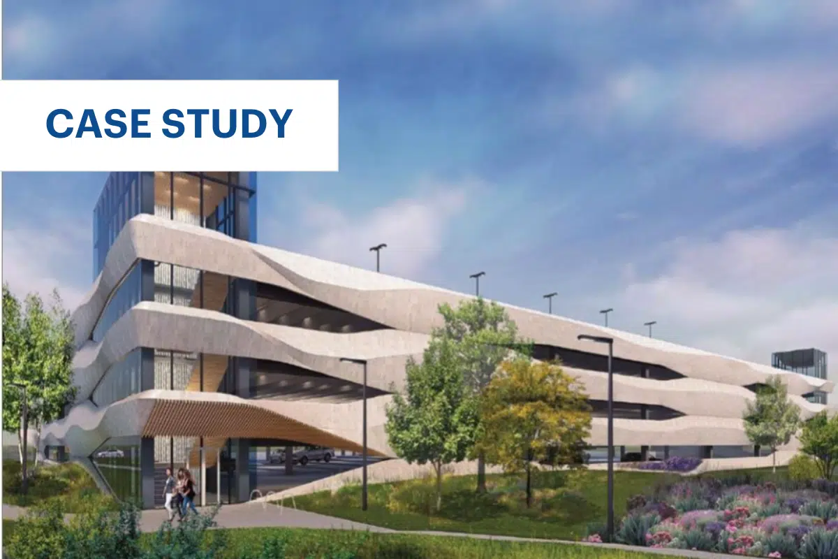
The $150 million high-rise office tower consists of a 14-story office building and below grade parking level with all glass curtain wall fascade. City leadership described the new HQ tower as a means to preserve the presence of the historic Houston company. The project also modified the public infrastructure along Allen Parkway and the Buffalo Bayou park.
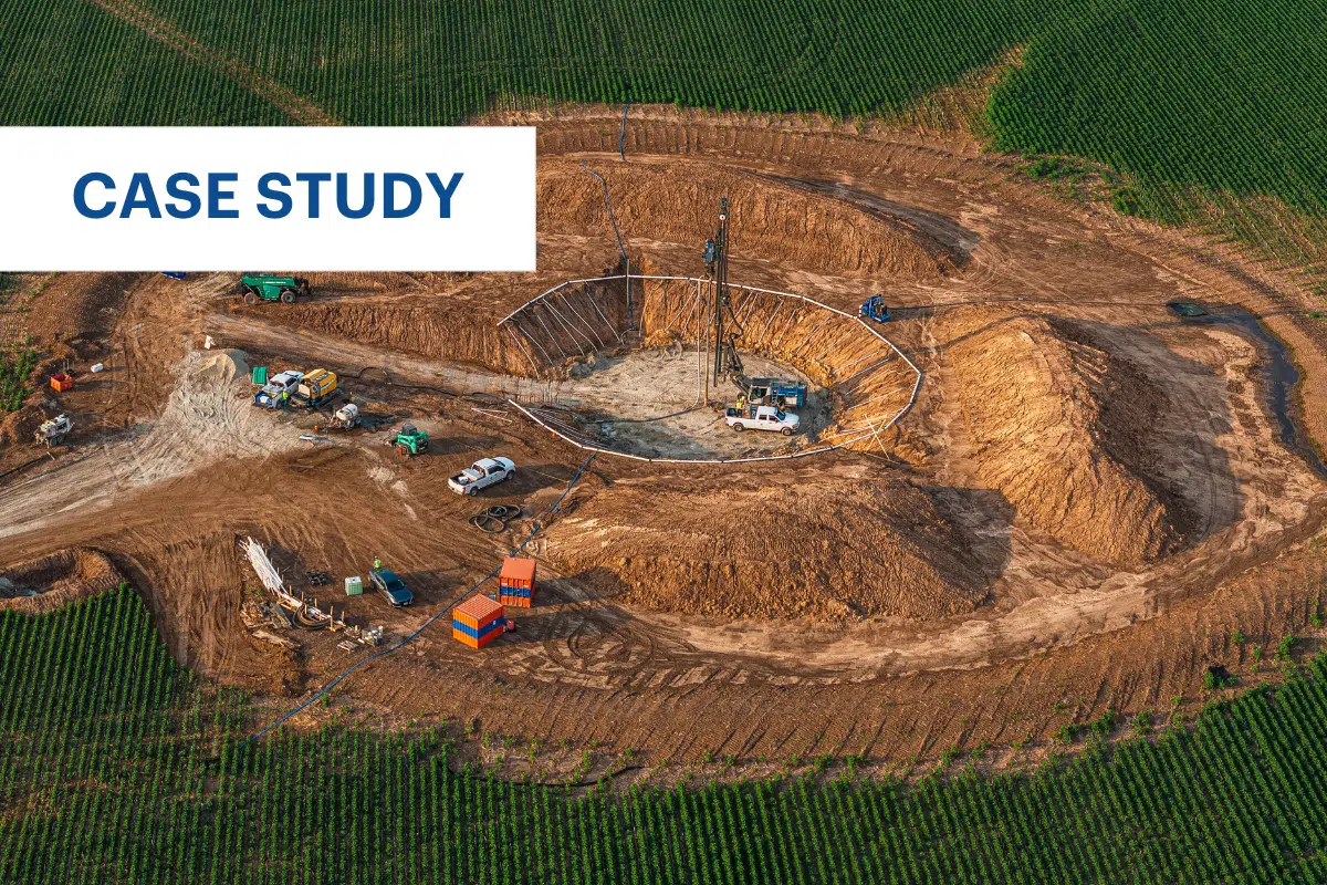
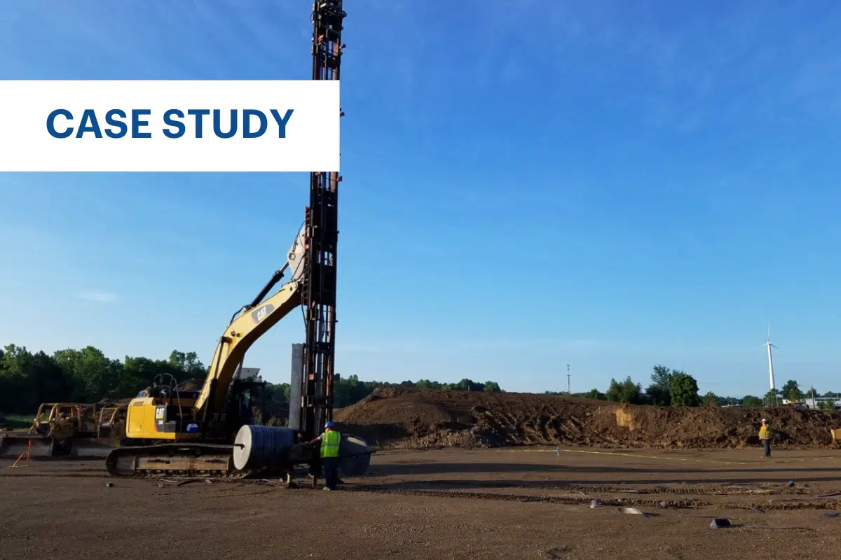
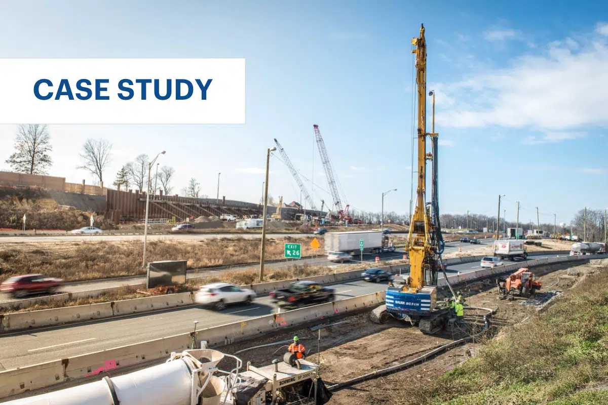
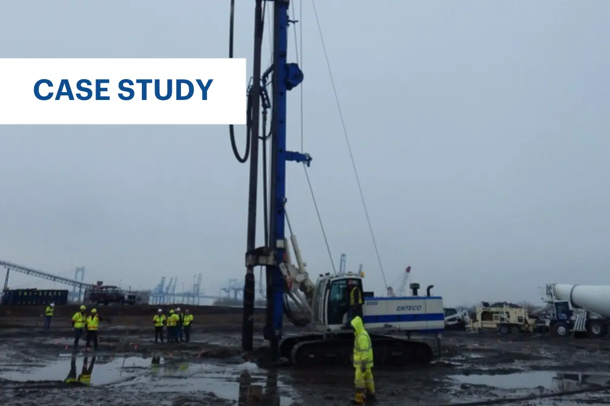
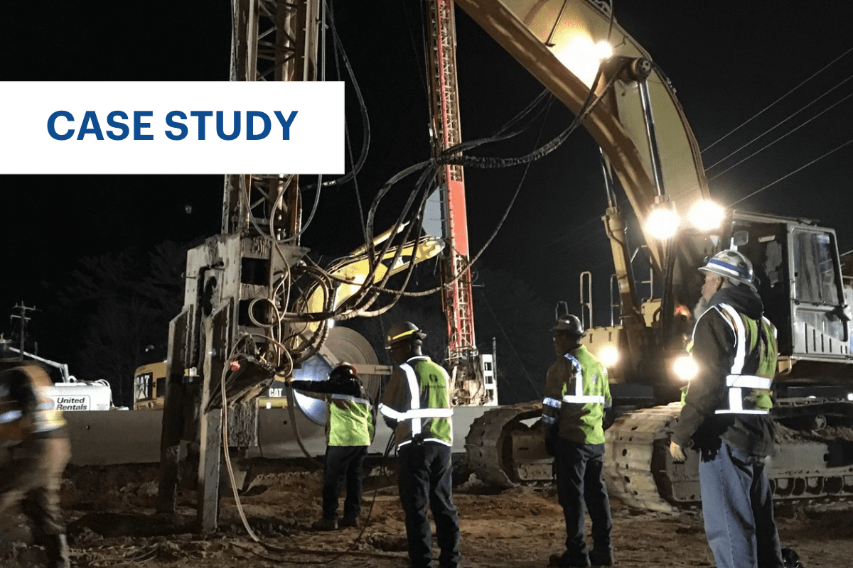
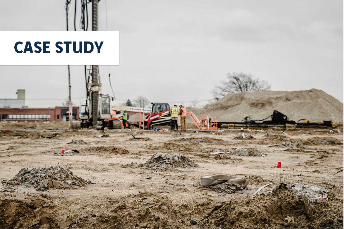
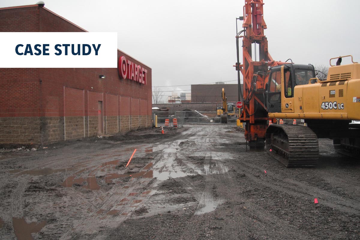
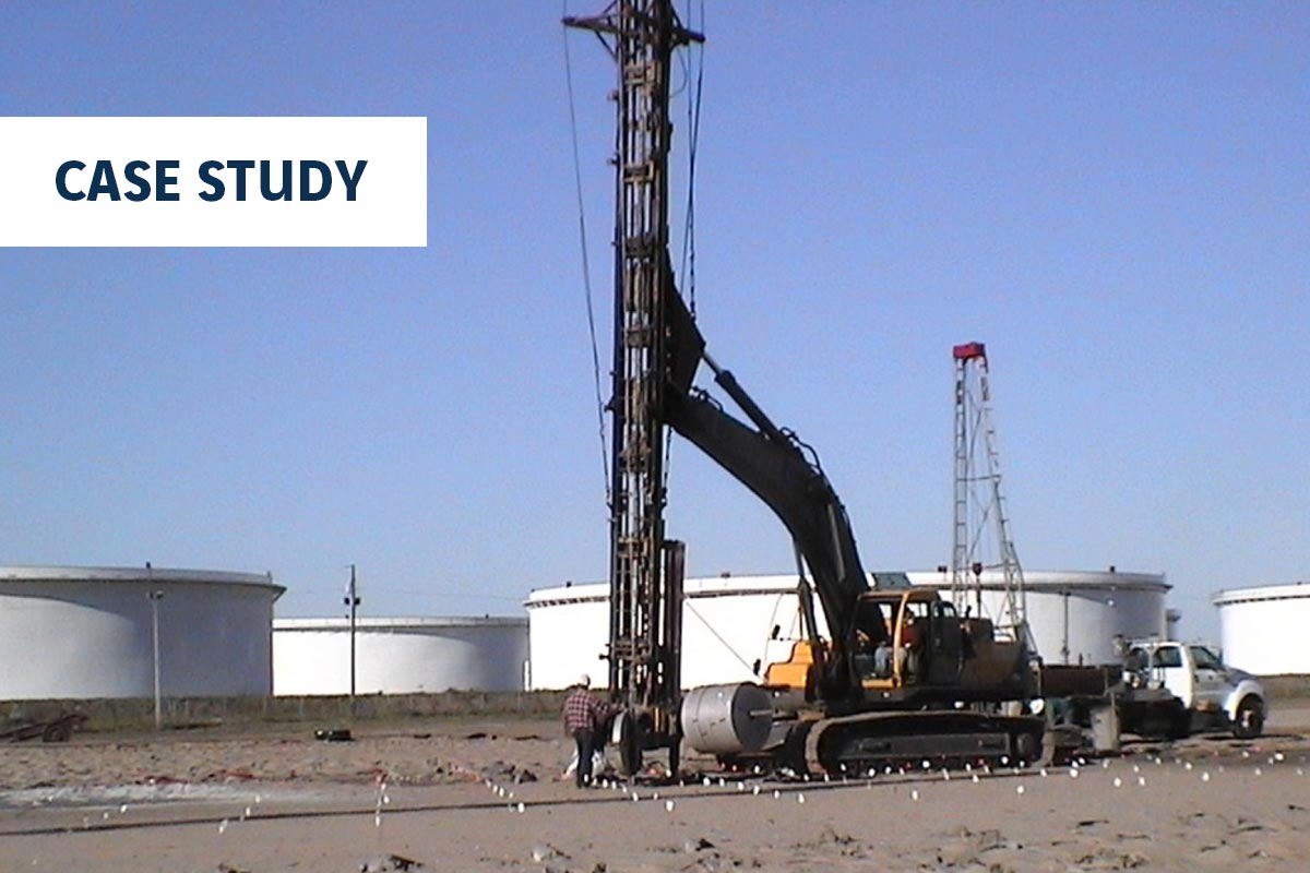
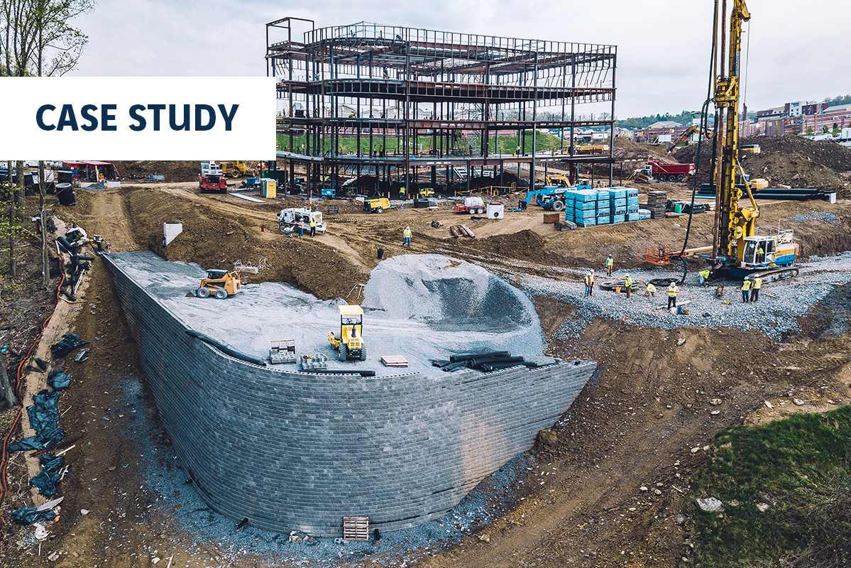
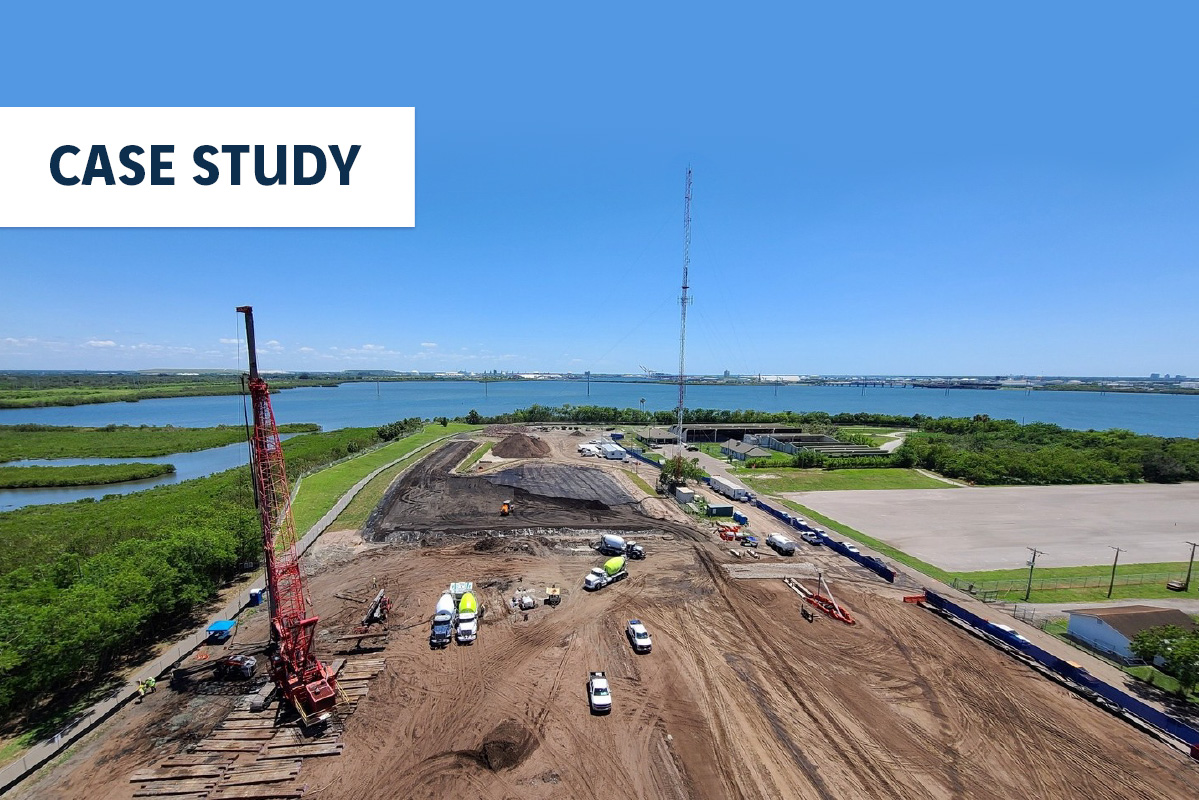
As the project was developed within the heart of the city atop a former building site, the geotechnical investigation noted the presence of deep uncontrolled fills. Additionally, the project is located on the banks of the Buffalo Bayou, which requires extensive, deep underground storm culverts to channel storm drainage to the bayou. The tower development was initially considered for augercast piles and drilled shafts due to the presence of buried culverts, deep uncontrolled fill, and settlement concerns. The project team and geotechnical engineer evaluated and selected Ground Improvement as a deep foundation alternative to address the concerns and meet building performance criteria.
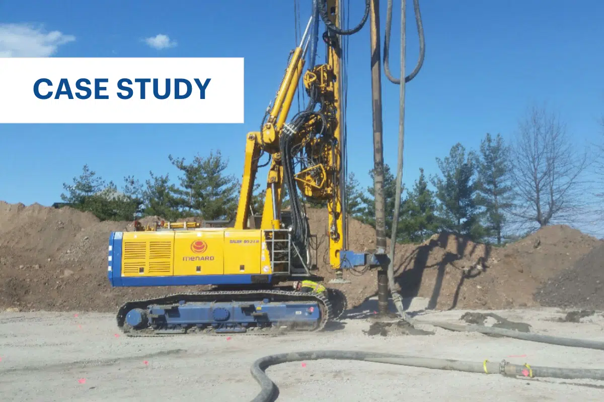
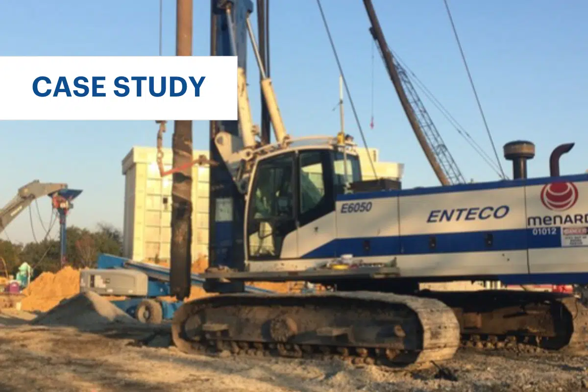
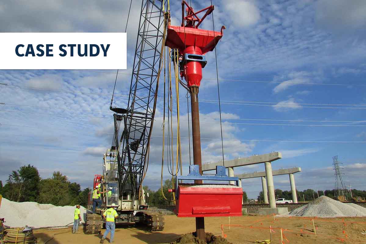
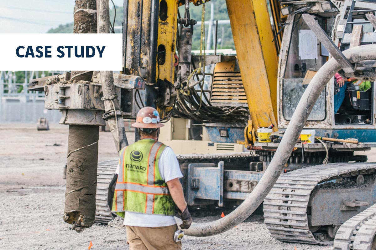
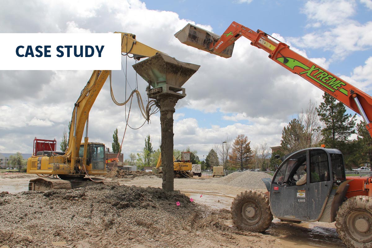
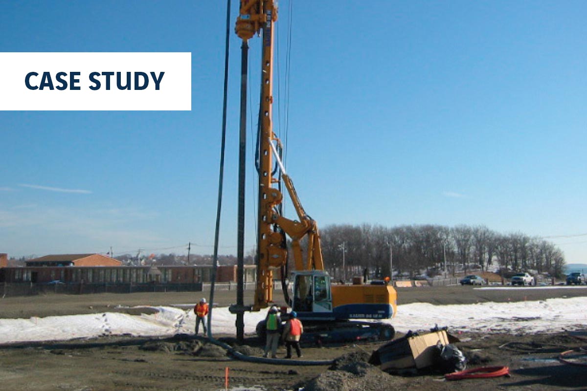
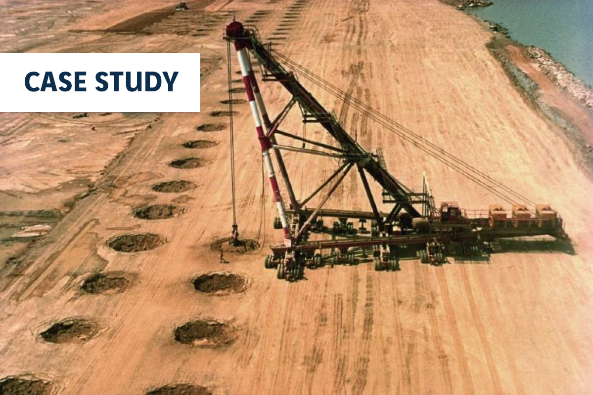
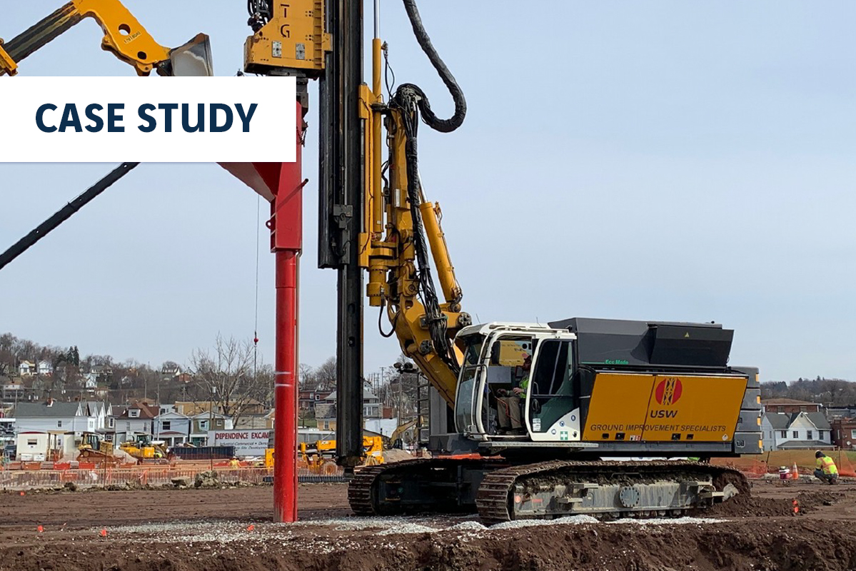
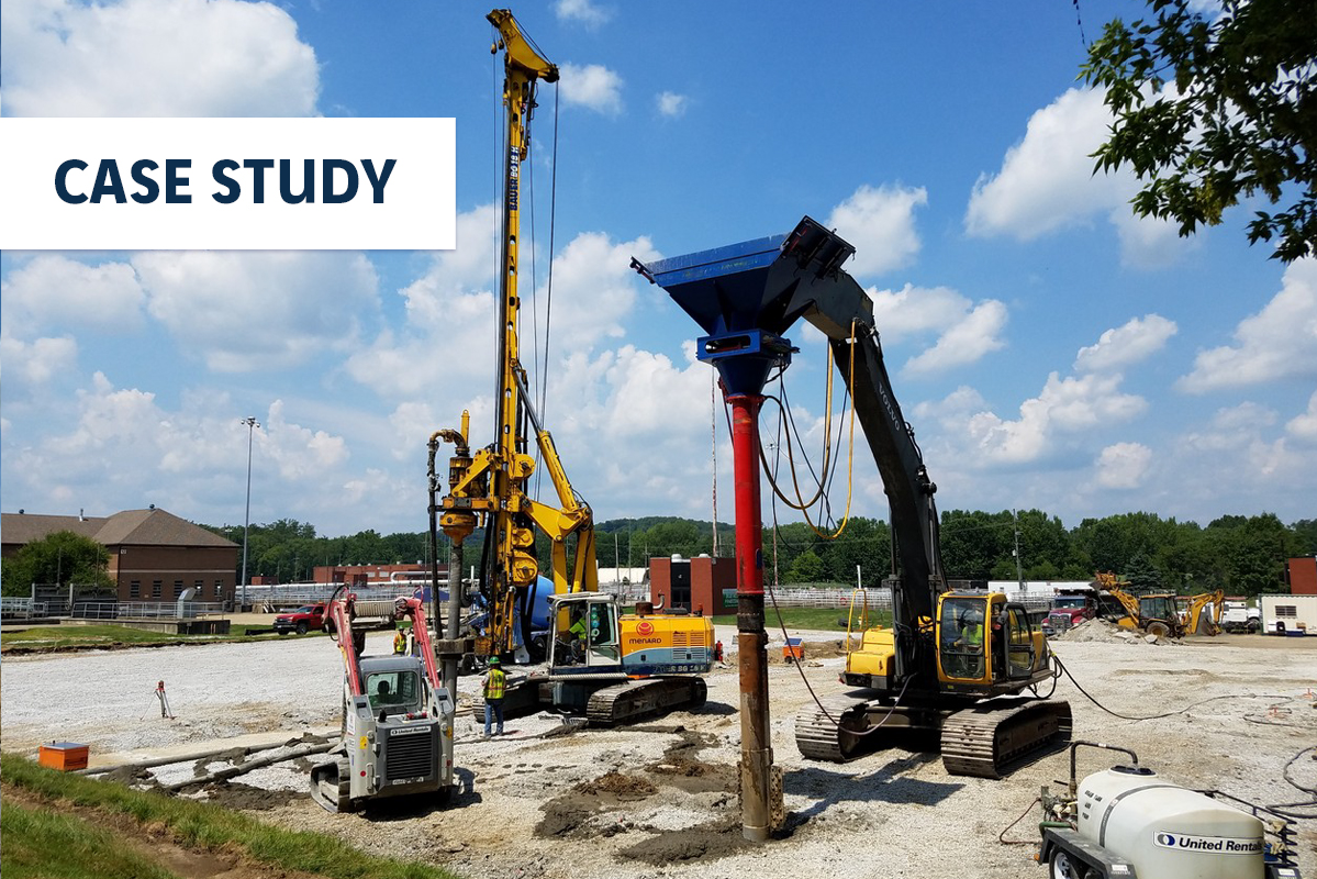
Menard was engaged by the Owner’s general contractors, who solicited competitive bid for ground improvement, and was awarded the scope. Menard evaluated the merits and costs of aggregate piers and Controlled Modulus Column (CMC)® rigid inclusions. Based on constructability, cost, and building performance, CMC rigid inclusions were selected for support of the new tower.
Ground Conditions:
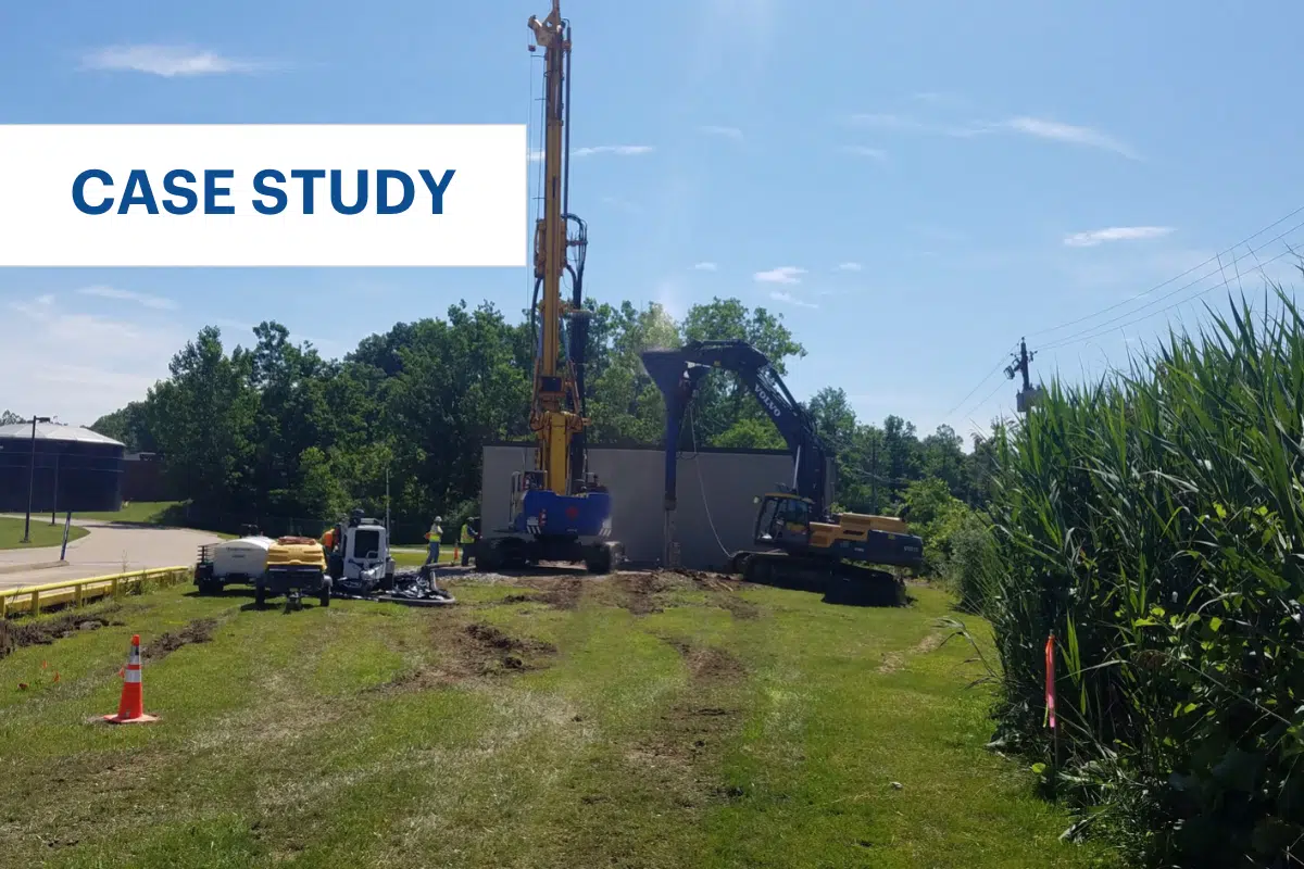
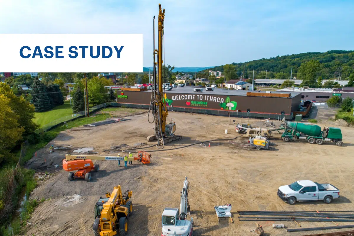
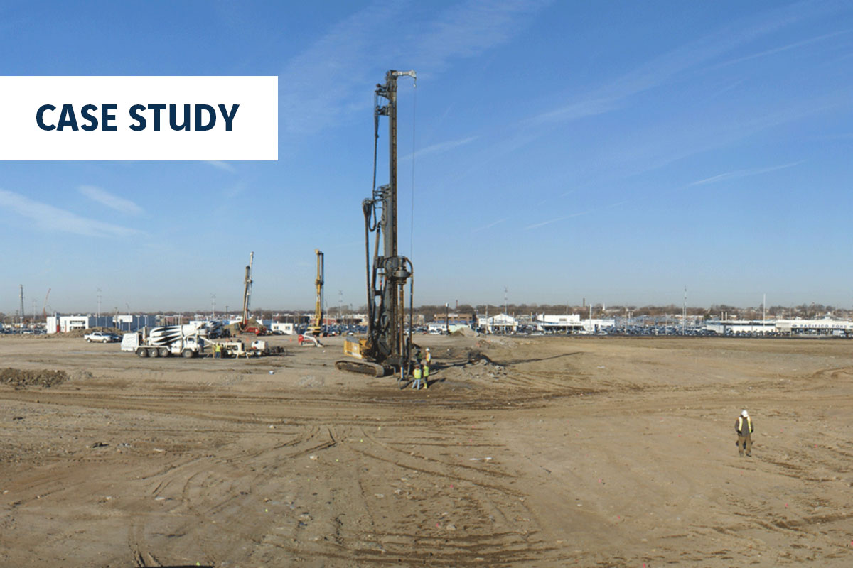
The site subgrade consisted of medium to very stiff sandy clays with layers of dense sand and silt. Up to 28 ft of controlled fill with obstructions and remnant deep foundations were present in portions of the site. The water table was ranged from 15 to 28 ft below ground surface. Several box culverts were present at depths of approximately 25 ft below existing site grades, which were located below the shallow foundations that required CMC rigid inclusion support. The owner requested the box culverts be left in place to avoid costly excavation and removal, which Menard was able to accommodate.
Solution:
Aggregate piers were initially considered for ground improvement. However, this method was deemed less suitable than CMC rigid inclusions for several reasons.
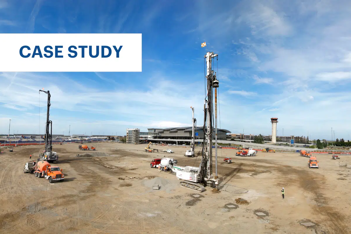
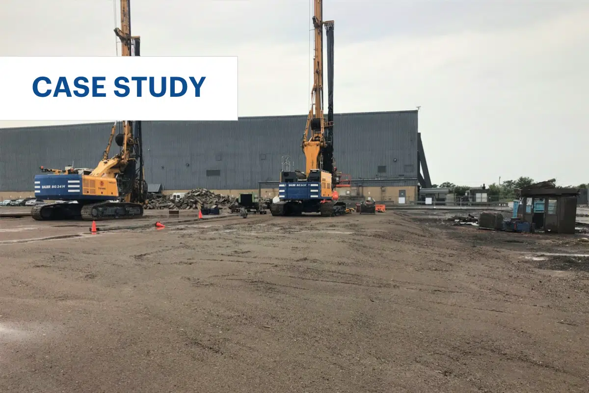
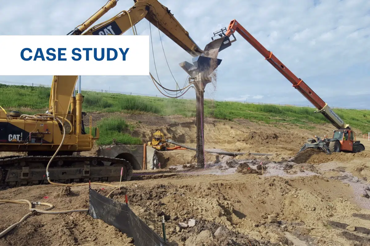
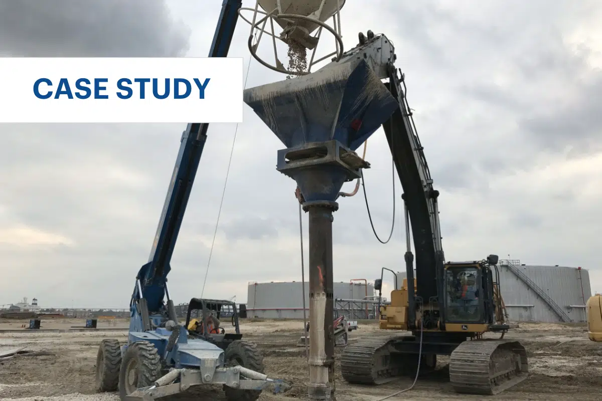
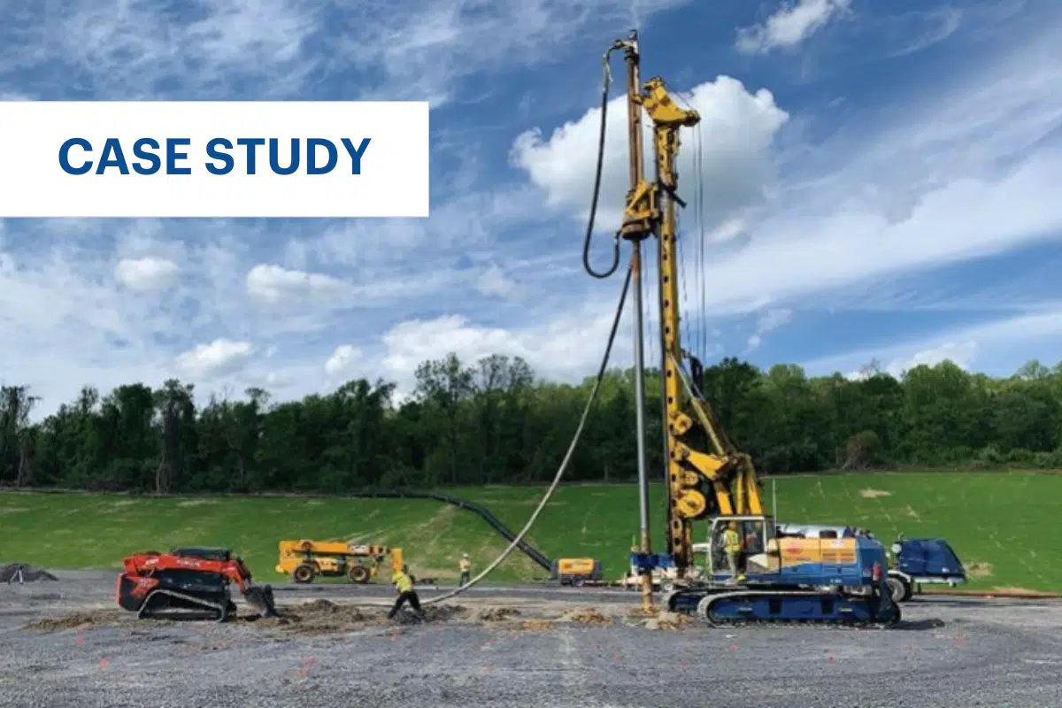
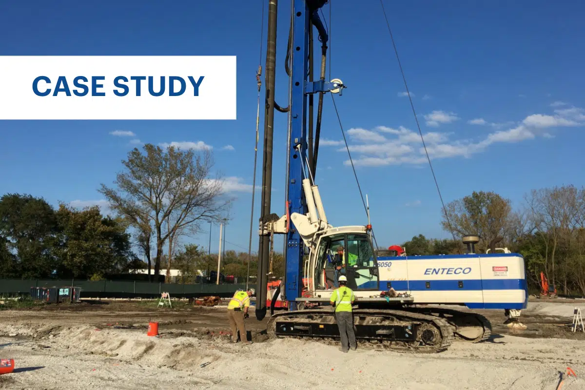
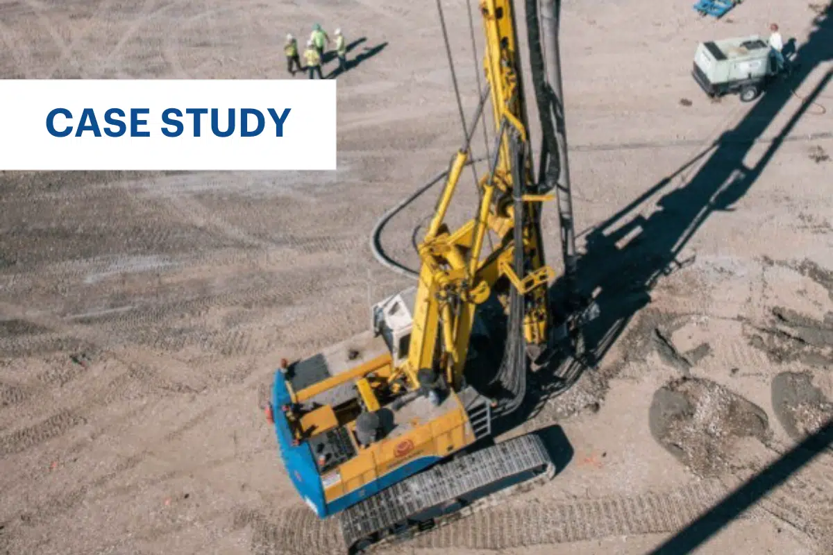
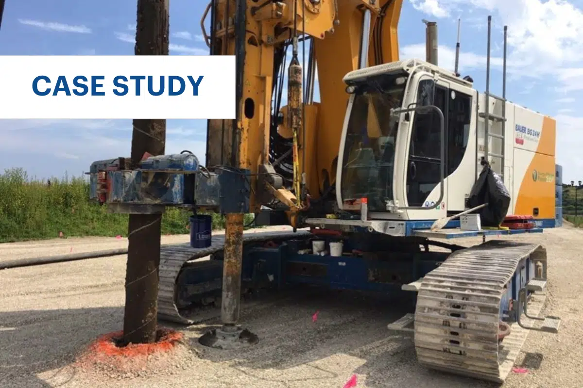
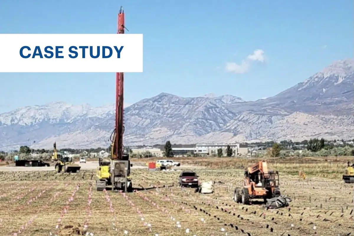
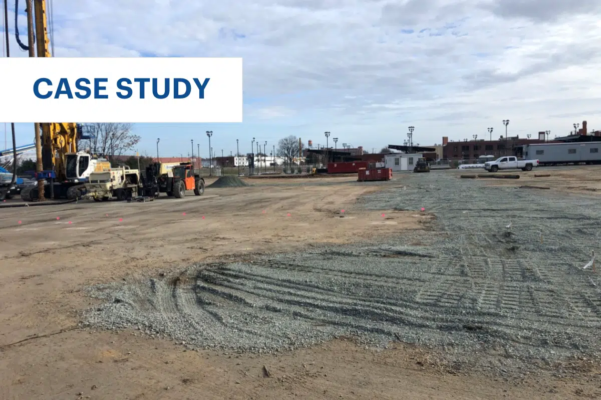
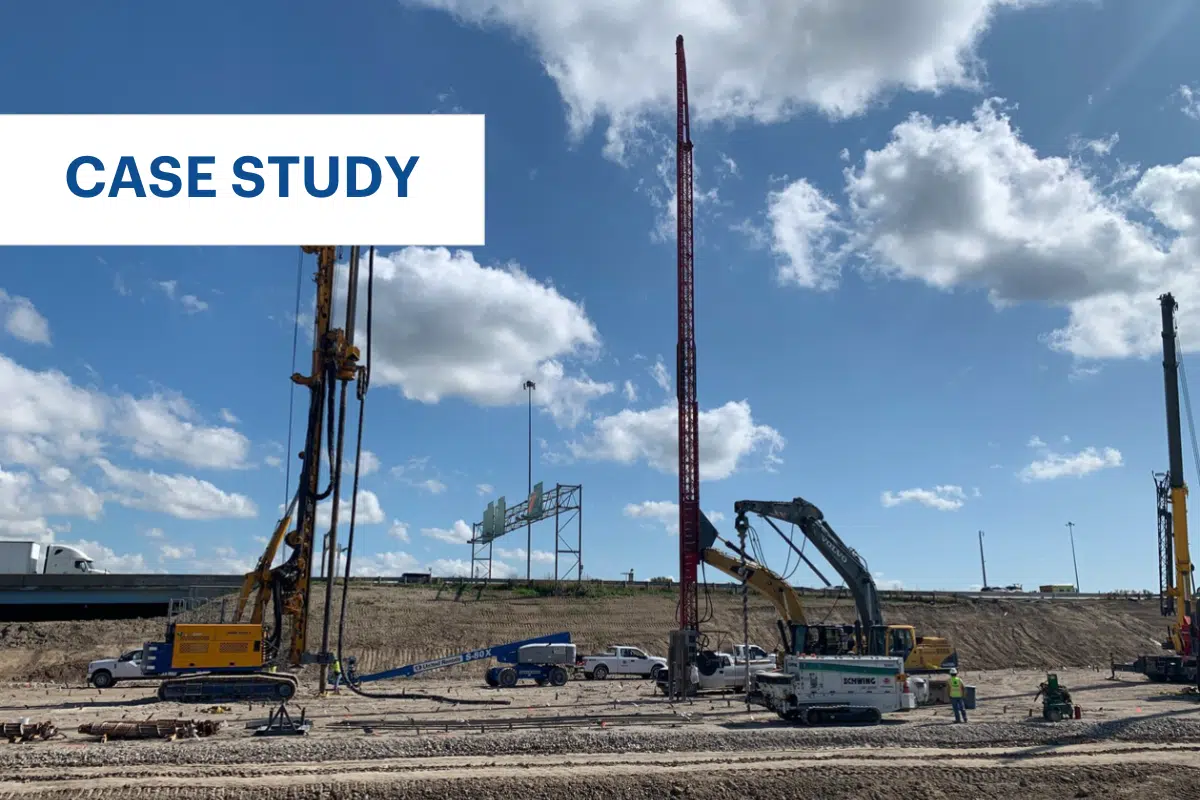
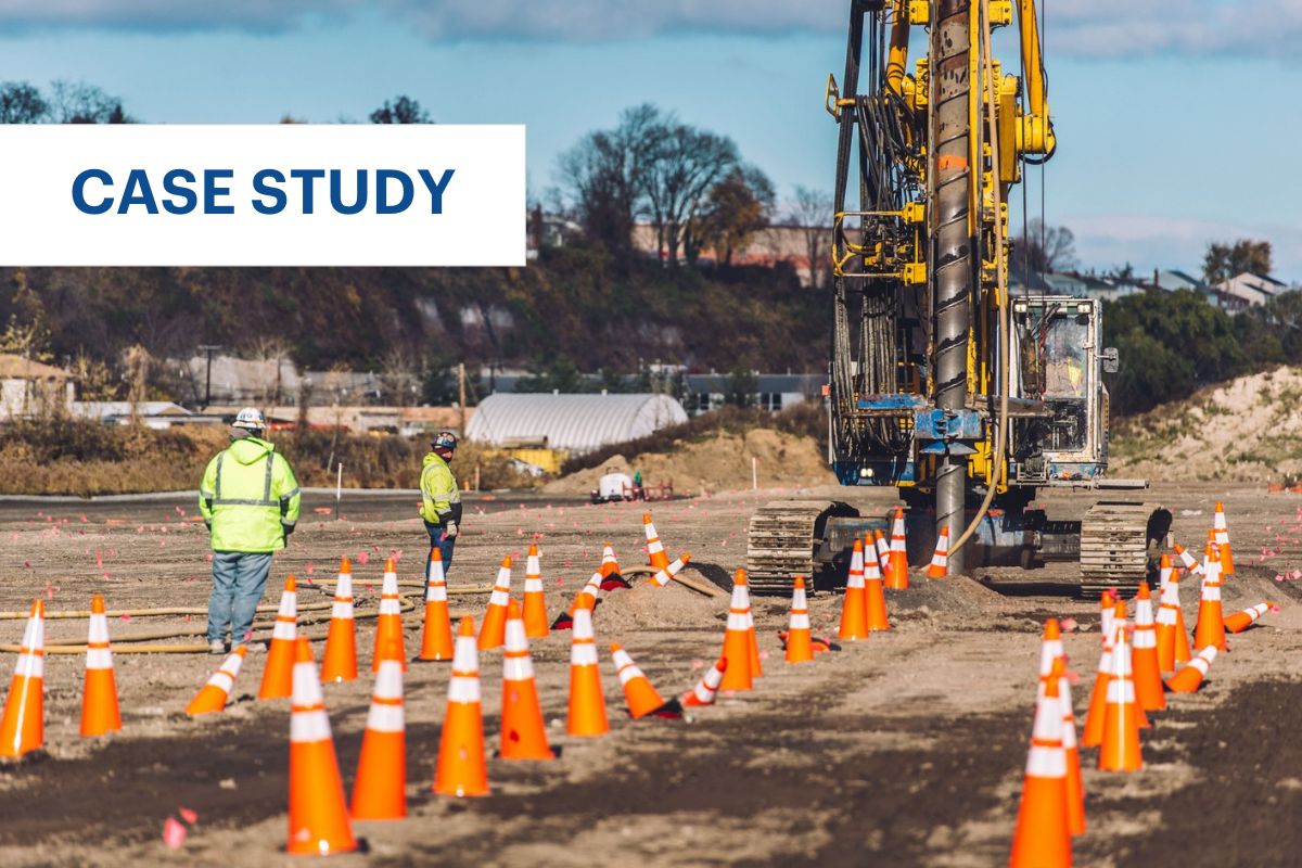
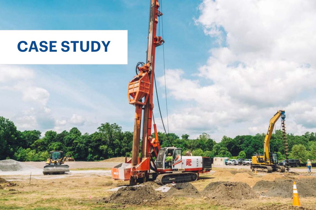
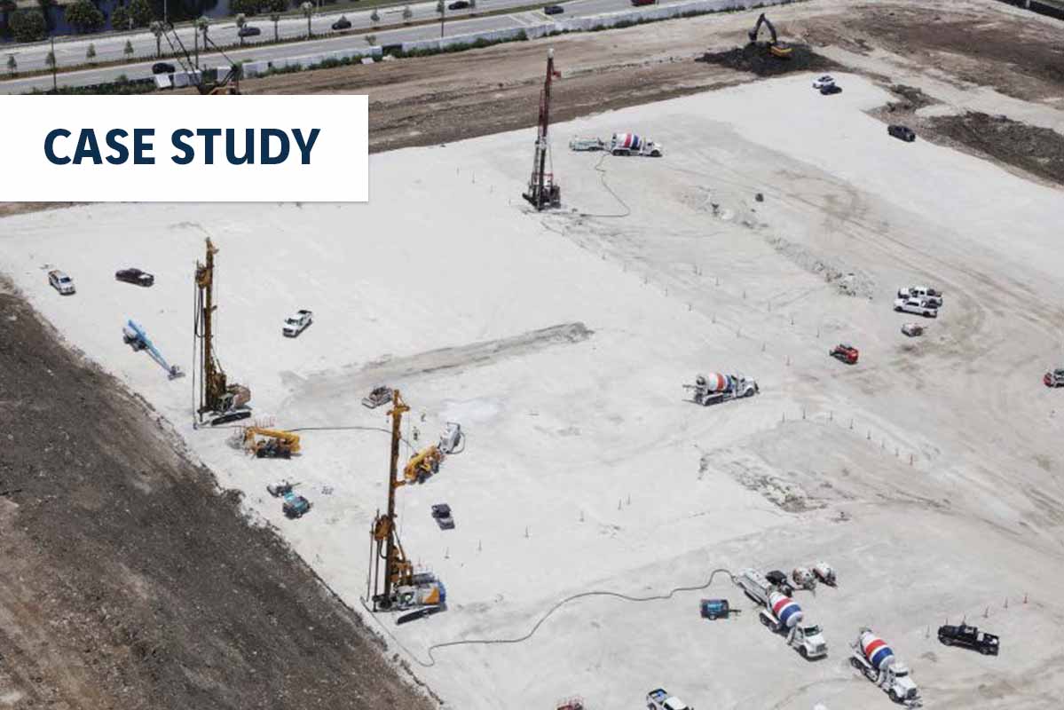
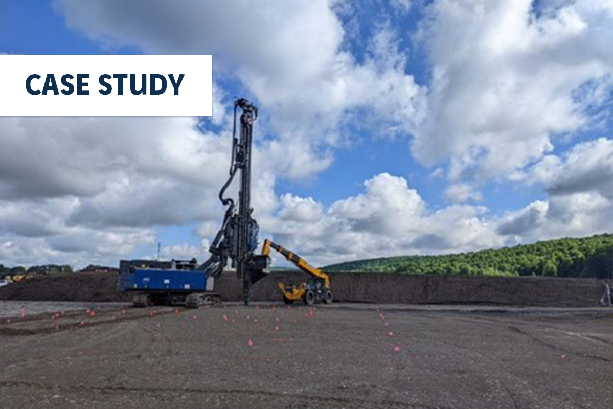
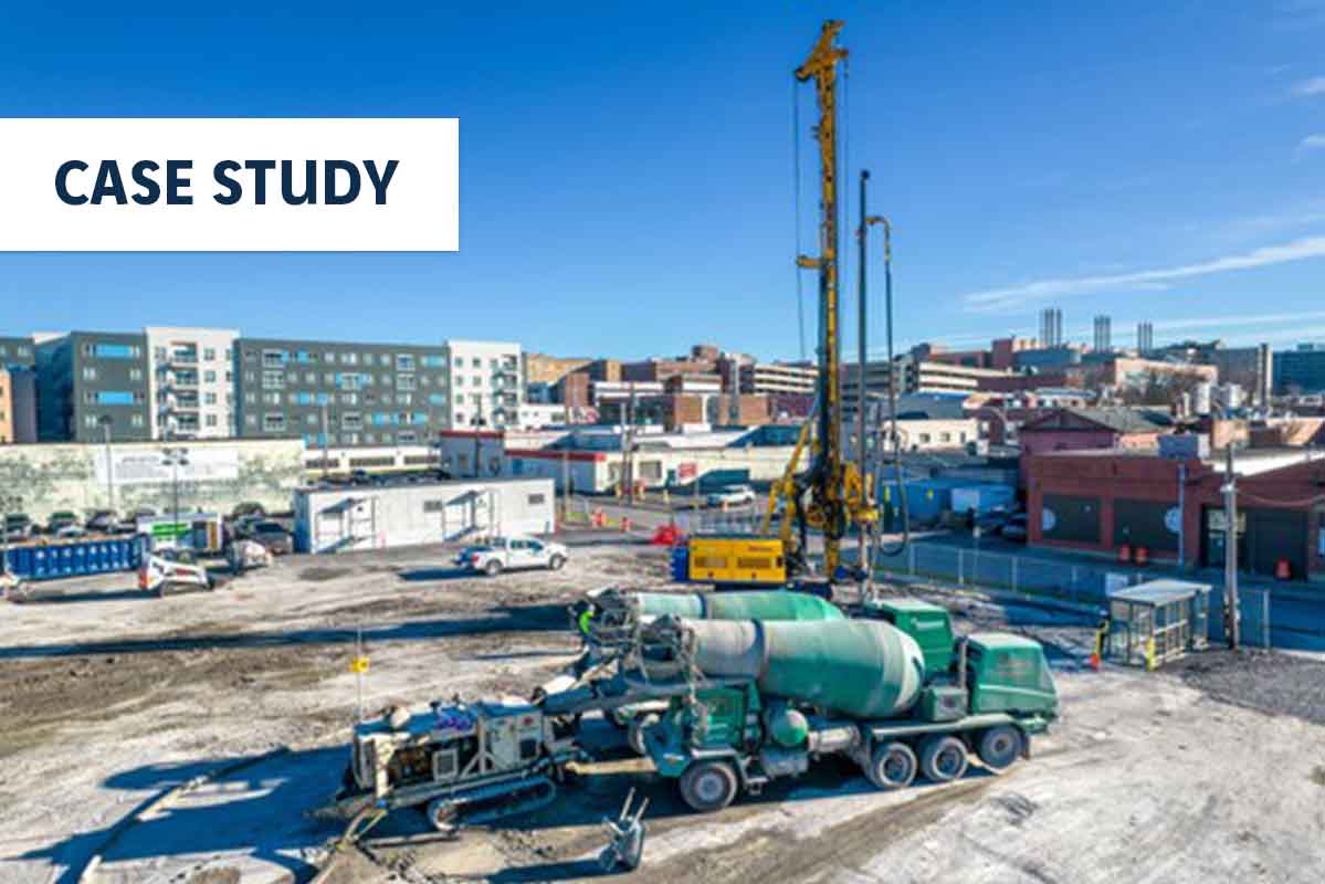
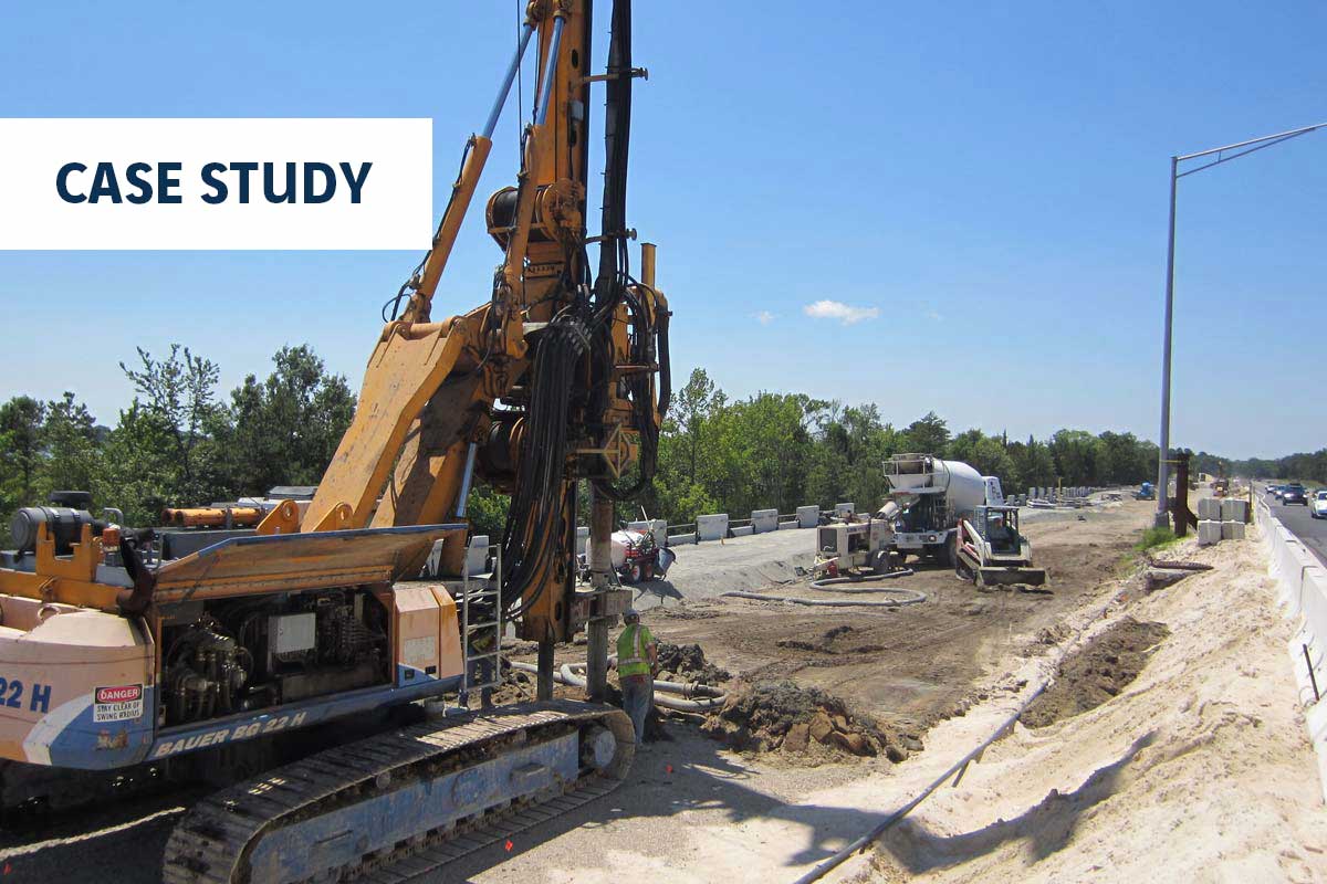
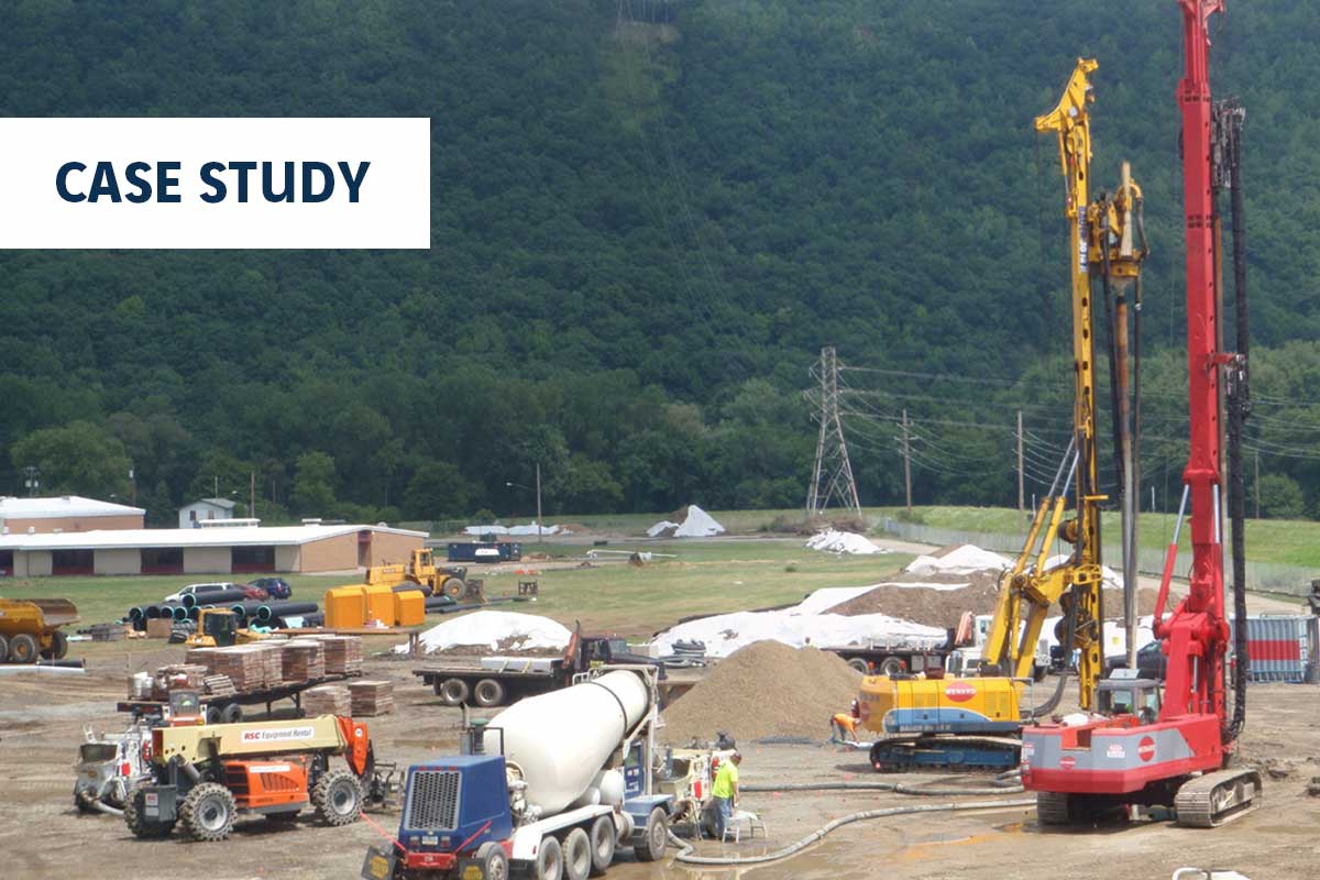
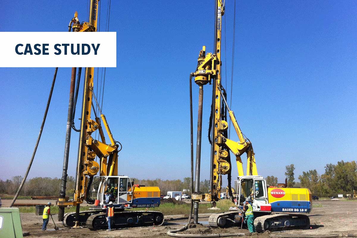
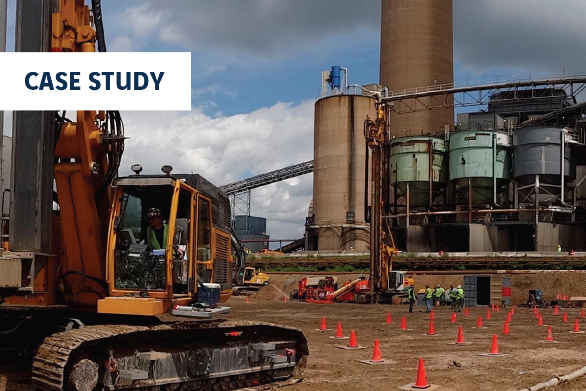
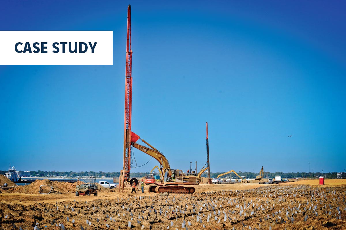
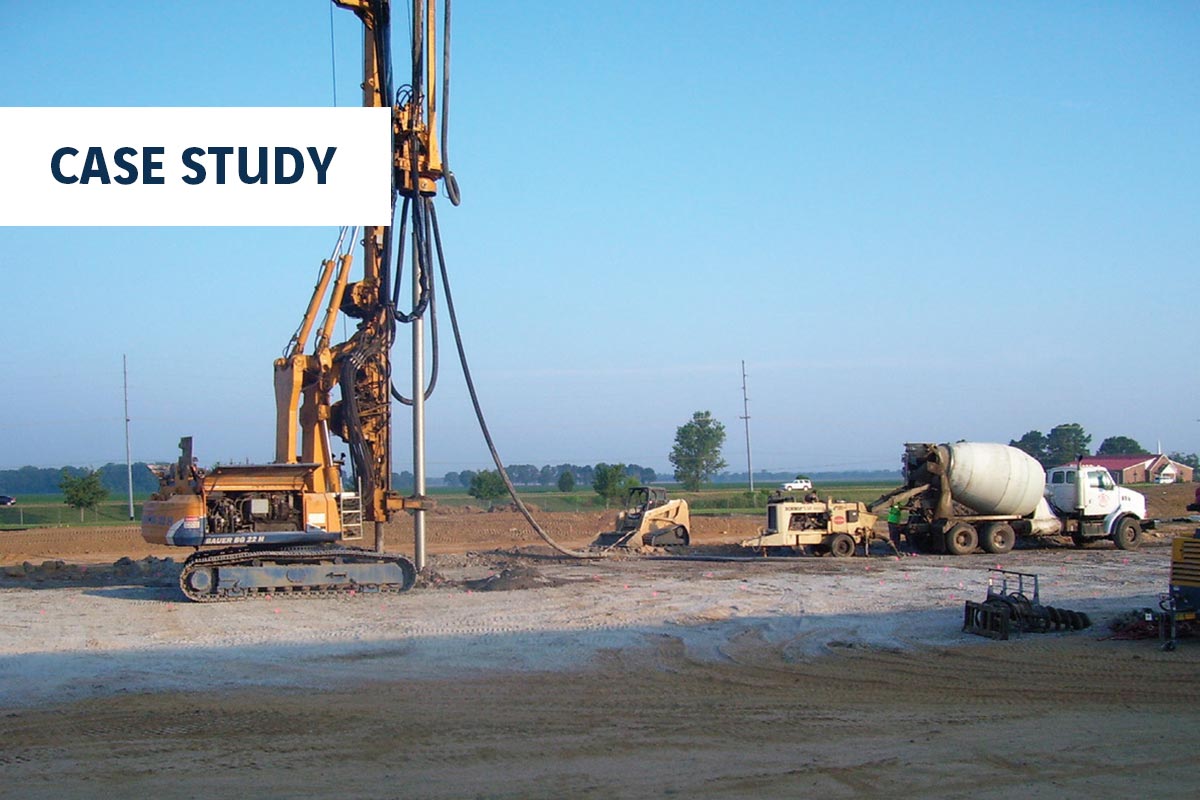
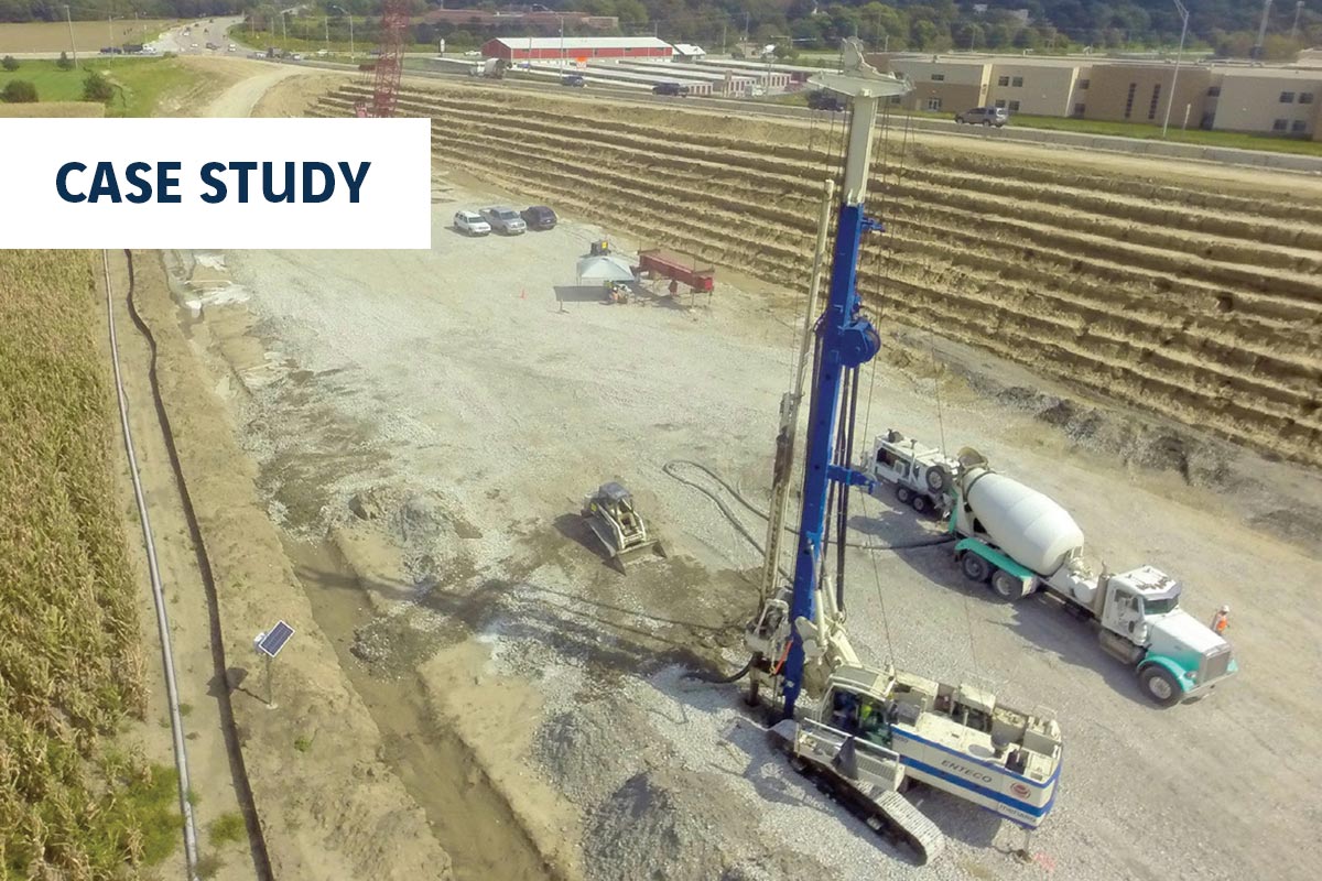
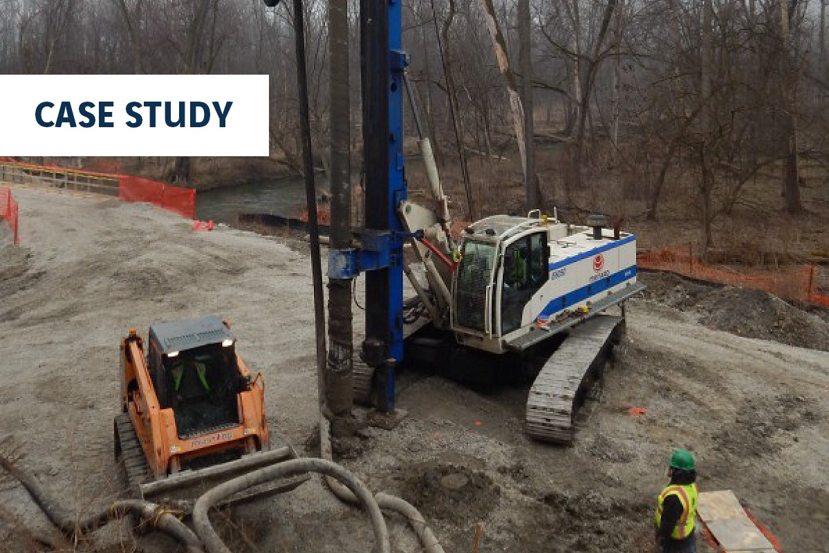
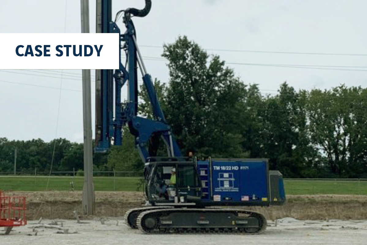
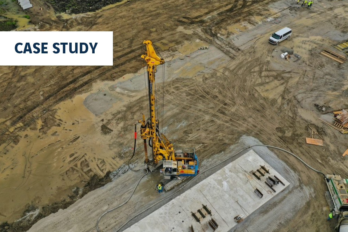
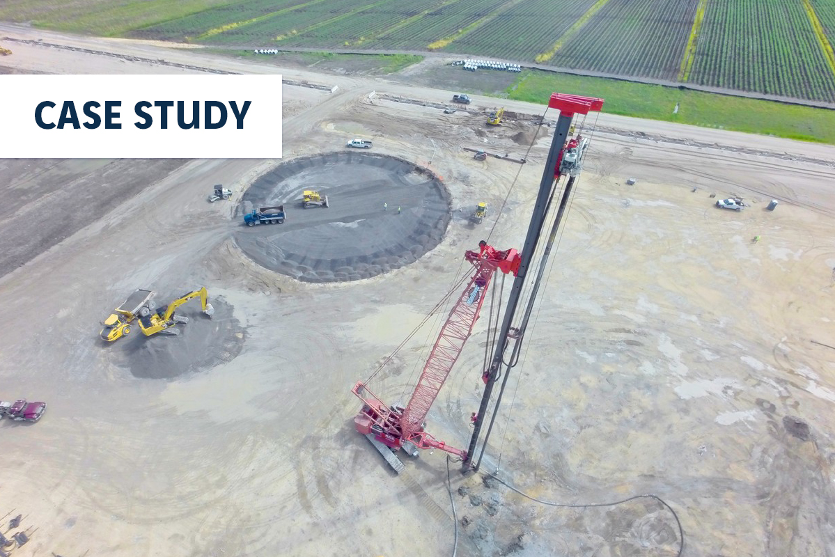
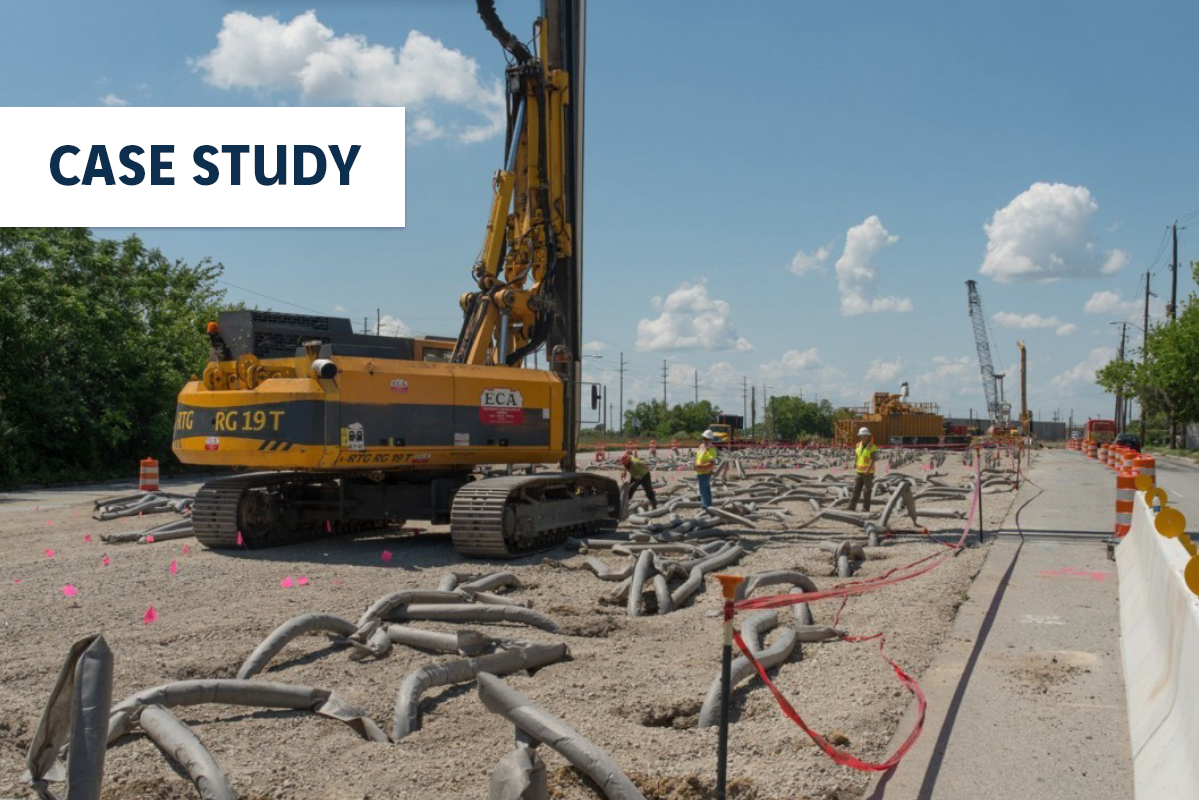
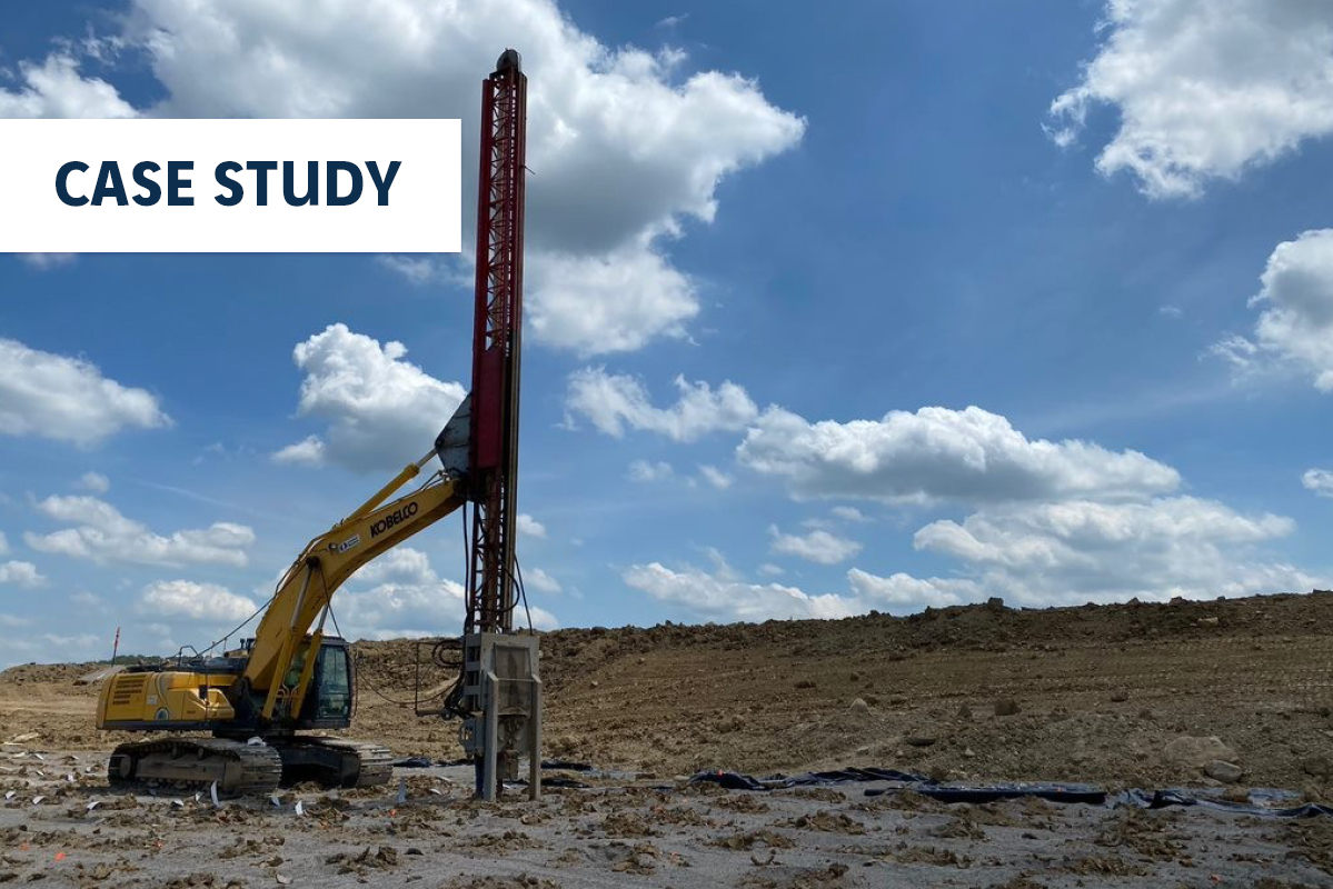
First, the total and differential settlements of the tower foundations were analyzed with an allowable bearing capacity of 9 ksf and estimated to be acceptable with CMC rigid inclusion support. Second, the load carrying capacity of the box culverts was a concern when subjected to the high bearing capacity of the tower footings. The box culvert was abandoned in place and CMC rigid inclusions were designed to extend foundation support below the culvert. Lastly, the presence of obstructions buried deep in the uncontrolled fill would have required an additional obstruction drill rig to facilitate predrilling for the aggregate piers (potentially up to three rigs onsite in a limited area). In Houston, Menard has performed CMC rigid inclusion installations in uncontrolled fill with similar buried obstructions. This meant the ground improvement installation could be performed with one CMC drill rig and allowed the GC to construct the concrete foundations in the same work area.
Approximately 810 CMCs were installed to an average depth of 35 ft in a 4-week schedule, ahead of the planned 5-week duration. Menard designed a layout of CMCs at each footing to support column loads up to 4,236 kips. The design provided for 1 ½ in of post-construction settlement with a ¾ in of differential settlement, meeting the performance criteria of the new tower.